## Diagram: Symbolic Engine Workflow with LLM Integration
### Overview
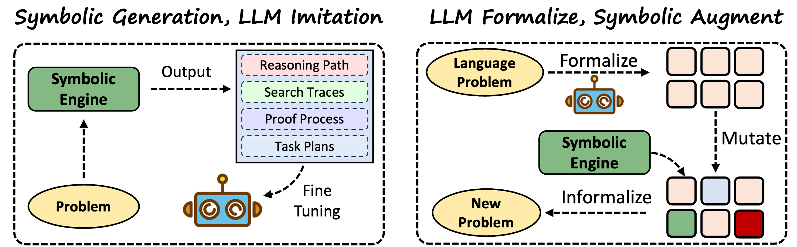
The image depicts two interconnected diagrams illustrating a symbolic engine's interaction with language models (LLMs). The left diagram focuses on "Symbolic Generation, LLM Imitation," while the right emphasizes "LLM Formalize, Symbolic Augment." Arrows indicate workflows, and colored boxes represent data or processes.
### Components/Axes
#### Left Diagram ("Symbolic Generation, LLM Imitation"):
- **Inputs**:
- `Problem` (oval, bottom-left).
- **Core Component**:
- `Symbolic Engine` (green rectangle, top-left).
- **Outputs**:
- `Reasoning Path` (pink rectangle).
- `Search Traces` (light green rectangle).
- `Proof Process` (purple rectangle).
- `Task Plans` (light blue rectangle).
- **Feedback Loop**:
- `Fine Tuning` (dashed arrow from outputs to `Problem`).
#### Right Diagram ("LLM Formalize, Symbolic Augment"):
- **Inputs**:
- `Language Problem` (oval, top-left).
- **Core Component**:
- `Symbolic Engine` (green rectangle, center).
- **Processes**:
- `Formalize` (dashed arrow from `Language Problem` to `Symbolic Engine`).
- `Mutate` (dashed arrow from `Symbolic Engine` to colored squares).
- `Informalize` (dashed arrow from colored squares to `New Problem`).
- **Outputs**:
- `New Problem` (oval, bottom-left).
- **Colored Squares**:
- 6 squares in a grid (top-right): 4 pink, 1 blue, 1 green.
- 3 squares in a grid (bottom-right): 2 pink, 1 green, 1 red.
### Detailed Analysis
#### Left Diagram:
- The `Symbolic Engine` processes a `Problem` and generates four outputs: `Reasoning Path`, `Search Traces`, `Proof Process`, and `Task Plans`.
- A feedback loop (`Fine Tuning`) suggests iterative refinement of the `Problem` using the engine's outputs.
#### Right Diagram:
- The `Language Problem` is formalized into the `Symbolic Engine`, which processes it and generates colored squares.
- The `Mutate` and `Informalize` steps transform these squares into a `New Problem`, implying a cycle of problem evolution.
- The colored squares (pink, blue, green, red) likely represent intermediate states or data points, though their exact meaning is unspecified.
### Key Observations
1. **Feedback Loops**: Both diagrams emphasize iterative refinement (`Fine Tuning` on the left, `Mutate/Informalize` on the right).
2. **Color Coding**: The right diagram uses colors (pink, blue, green, red) to differentiate stages or data types, but no legend clarifies their meaning.
3. **Divergent Workflows**:
- Left: Focuses on symbolic output generation and problem refinement.
- Right: Focuses on formalizing language problems and augmenting via symbolic processing.
### Interpretation
The diagrams illustrate a hybrid system where LLMs and symbolic engines collaborate. The left diagram highlights how symbolic reasoning outputs (e.g., task plans, proofs) refine LLM-generated problems. The right diagram shows how LLMs formalize problems, which are then processed symbolically and mutated to generate new problems. The colored squares in the right diagram may represent diverse data points or problem features, with mutation and informalization enabling creative problem evolution.
**Notable Patterns**:
- The `Symbolic Engine` acts as a central hub in both workflows, bridging LLMs and symbolic reasoning.
- The absence of explicit labels for colored squares suggests they are abstract representations of intermediate states.
- The feedback loops imply a dynamic, self-improving system.
**Underlying Logic**:
- Symbolic engines provide structured reasoning to augment LLM outputs, addressing limitations like hallucination or lack of formal logic.
- The workflows suggest a pipeline where LLMs generate initial hypotheses, symbolic engines validate/refine them, and the cycle repeats to improve problem-solving.