## Flow Diagram: Lean-SMT Tactic
### Overview
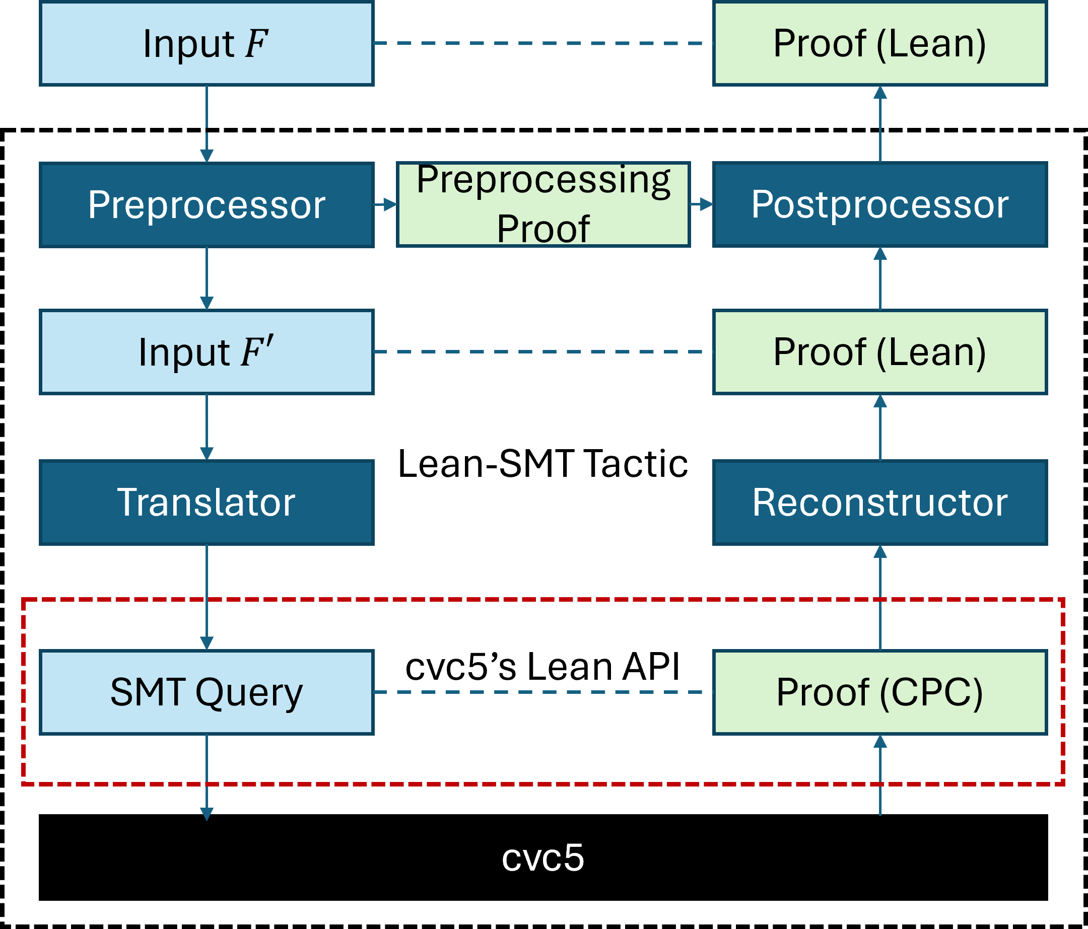
The image is a flow diagram illustrating the Lean-SMT Tactic, detailing the process from input to proof generation using cvc5. The diagram shows the flow of data and transformations through various components, including preprocessors, translators, and reconstructors, ultimately leading to a proof.
### Components/Axes
* **Boxes:** Represent processes or data.
* Light Blue Boxes: Represent Input or Queries
* Dark Blue Boxes: Represent Processors or Translators
* Light Green Boxes: Represent Proofs
* **Arrows:** Indicate the direction of data flow.
* Solid Arrows: Represent direct data flow
* Dashed Arrows: Represent a connection or API usage
* **Text Labels:** Describe the function or data within each box.
* **Bounding Boxes:**
* Dashed Black Box: Encloses the entire Lean-SMT Tactic process.
* Dashed Red Box: Encloses the cvc5's Lean API interaction.
### Detailed Analysis or ### Content Details
1. **Top Row:**
* `Input F` (Light Blue Box, top-left): Represents the initial input.
* Dashed Blue Arrow: Connects `Input F` to `Proof (Lean)`.
* `Proof (Lean)` (Light Green Box, top-right): Represents the final proof in Lean.
2. **Second Row (within dashed black box):**
* `Preprocessor` (Dark Blue Box, left): Processes the initial input.
* Arrow: Connects `Preprocessor` to `Preprocessing Proof`.
* `Preprocessing Proof` (Light Green Box, center): Represents the proof generated during preprocessing.
* Arrow: Connects `Preprocessing Proof` to `Postprocessor`.
* `Postprocessor` (Dark Blue Box, right): Processes the preprocessed proof.
* Arrow: Connects `Postprocessor` to `Proof (Lean)` in the top row.
3. **Third Row:**
* `Input F'` (Light Blue Box, left): Represents a transformed input.
* Dashed Blue Arrow: Connects `Input F'` to `Proof (Lean)`.
* `Proof (Lean)` (Light Green Box, right): Represents the final proof in Lean.
4. **Fourth Row (labeled "Lean-SMT Tactic"):**
* `Translator` (Dark Blue Box, left): Translates the input.
* `Reconstructor` (Dark Blue Box, right): Reconstructs the proof.
5. **Fifth Row (within dashed red box, labeled "cvc5's Lean API"):**
* `SMT Query` (Light Blue Box, left): Represents the SMT query.
* `Proof (CPC)` (Light Green Box, right): Represents the proof in CPC format.
6. **Bottom Row:**
* `cvc5` (Black Box): Represents the cvc5 solver.
7. **Arrows:**
* Downward Arrow: Connects `Preprocessor` to `Input F'`.
* Downward Arrow: Connects `Input F'` to `Translator`.
* Downward Arrow: Connects `Translator` to `SMT Query`.
* Horizontal Dashed Blue Arrow: Connects `SMT Query` to `Proof (CPC)`.
* Upward Arrow: Connects `Proof (CPC)` to `Reconstructor`.
* Upward Arrow: Connects `Reconstructor` to `Proof (Lean)`.
* Downward Arrow: Connects `SMT Query` to `cvc5`.
* Upward Arrow: Connects `cvc5` to `Proof (CPC)`.
### Key Observations
* The diagram illustrates a multi-stage process for generating proofs using the Lean-SMT tactic.
* The process involves preprocessing, translation, and reconstruction steps.
* The cvc5 solver plays a crucial role in generating proofs in CPC format.
* The Lean API of cvc5 is used to interact with the solver.
* The diagram highlights the flow of data and transformations between different components.
### Interpretation
The diagram provides a high-level overview of the Lean-SMT tactic, showcasing how it leverages the cvc5 solver to generate proofs. The process starts with an initial input `F`, which is preprocessed and potentially transformed into `F'`. The transformed input is then translated into an SMT query, which is passed to the cvc5 solver. The solver generates a proof in CPC format, which is then reconstructed into a Lean proof. The diagram emphasizes the modularity of the process, with distinct components responsible for preprocessing, translation, reconstruction, and solving. The use of the cvc5 Lean API allows for seamless integration between the Lean theorem prover and the cvc5 solver. The dashed boxes visually group related components, highlighting the different stages of the proof generation process.