\n
## Diagram: System Architecture for Automated Theorem Proving
### Overview
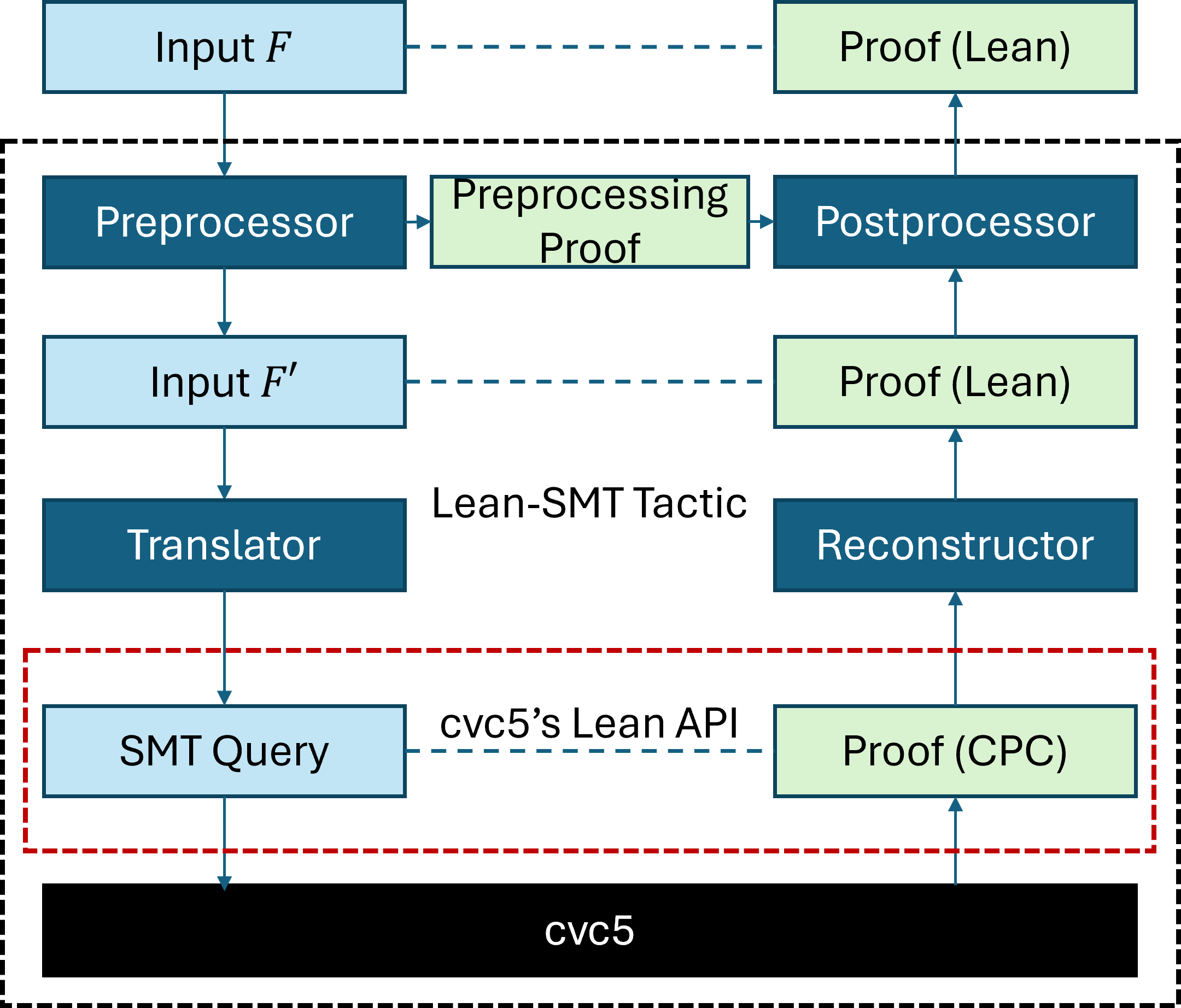
The image depicts a system architecture diagram illustrating the flow of data and processes involved in automated theorem proving, specifically within the context of the `cvc5` system. The diagram shows a series of processing stages, transformations, and interactions between different components. The overall structure is hierarchical, with `cvc5` at the base and progressively more abstract layers above.
### Components/Axes
The diagram consists of the following components:
* **Input F:** The initial input formula.
* **Preprocessor:** A component that processes the input formula.
* **Input F':** The preprocessed input formula.
* **Translator:** A component that translates the preprocessed formula.
* **SMT Query:** The translated formula in SMT (Satisfiability Modulo Theories) format.
* **cvc5:** The core SMT solver.
* **Lean-SMT Tactic:** A tactic used to interact with the SMT solver.
* **Reconstructor:** A component that reconstructs the proof.
* **Postprocessor:** A component that postprocesses the proof.
* **Preprocessing Proof:** Proof generated during preprocessing.
* **Proof (Lean):** Proof in the Lean theorem prover format.
* **Proof (CPC):** Proof in the CPC (Counterexample Proof Certificate) format.
* **cvc5's Lean API:** The interface between the Lean-SMT tactic and `cvc5`.
The diagram uses dashed arrows to indicate data flow and solid arrows to indicate process flow. The components are visually grouped within dashed-line boxes, suggesting functional modules.
### Detailed Analysis or Content Details
The diagram illustrates the following flow:
1. **Input:** The process begins with an input formula, labeled "Input F".
2. **Preprocessing:** "Input F" is passed to the "Preprocessor", which generates "Input F'". A "Preprocessing Proof" is also generated during this stage.
3. **Translation:** "Input F'" is then passed to the "Translator", which converts it into an "SMT Query".
4. **SMT Solving:** The "SMT Query" is sent to the "cvc5" solver via "cvc5's Lean API".
5. **Lean-SMT Tactic:** The "Lean-SMT Tactic" interacts with `cvc5` to obtain a proof.
6. **Reconstruction & Postprocessing:** The proof is then passed to the "Reconstructor", which generates a "Proof (Lean)". This "Proof (Lean)" is then passed to the "Postprocessor", which generates another "Proof (Lean)".
7. **CPC Proof:** Simultaneously, a "Proof (CPC)" is generated directly from `cvc5`.
8. **Output:** Finally, "Proof (Lean)" is outputted.
The diagram shows a bidirectional flow between the "Preprocessor" and "Input F", and between the "Postprocessor" and "Proof (Lean)".
### Key Observations
The diagram highlights the integration of `cvc5` with the Lean theorem prover. The process involves multiple transformations of the input formula and proof, suggesting a complex workflow. The presence of both "Proof (Lean)" and "Proof (CPC)" indicates support for different proof formats. The dashed lines suggest asynchronous or indirect data flow.
### Interpretation
This diagram represents a system designed to leverage the strengths of both an SMT solver (`cvc5`) and a formal proof assistant (Lean). The `cvc5` solver is used to find a solution or counterexample to a given problem, while the Lean theorem prover is used to formally verify the correctness of the solution. The diagram illustrates how the system translates between these two worlds, converting the SMT solver's output into a format that can be understood and verified by the Lean theorem prover. The multiple proof formats suggest flexibility in how the results can be used. The preprocessing and postprocessing steps likely involve optimizations and transformations to improve the efficiency and readability of the proofs. The bidirectional arrows suggest feedback loops, potentially for refinement or error correction. The overall architecture suggests a robust and sophisticated system for automated theorem proving.