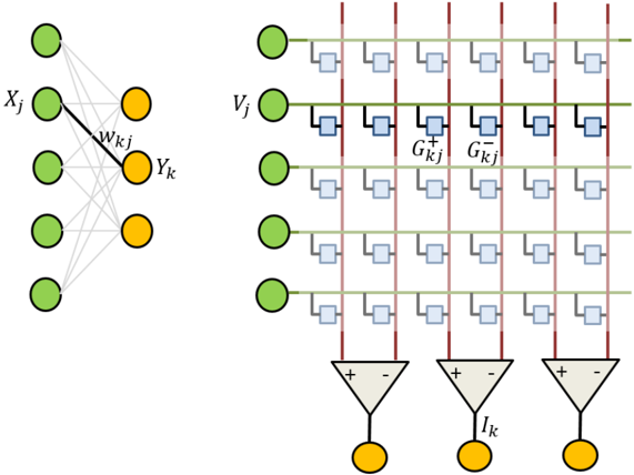
## Neural Network Diagram: Conceptual Model and Hardware Implementation
### Overview
The image presents a conceptual diagram of a neural network and a corresponding hardware implementation. The left side illustrates the weighted connections between input and output neurons, while the right side depicts a potential hardware architecture using memristors to represent synaptic weights.
### Components/Axes
**Left Side (Conceptual Model):**
* **Nodes:** Green circles represent input neurons (labeled Xj), and orange circles represent output neurons (labeled Yk).
* **Connections:** Gray lines represent connections between input and output neurons. A thicker black line represents a specific connection with weight wkj.
**Right Side (Hardware Implementation):**
* **Input Neurons:** Green circles represent input neurons (labeled Vj).
* **Output Neurons:** Orange circles represent output neurons (labeled Ik).
* **Memristor Array:** A grid of light blue squares represents memristors, which store the synaptic weights.
* **Horizontal Lines:** Green lines represent the input lines.
* **Vertical Lines:** Red lines represent the output lines.
* **Differential Amplifiers:** Gray triangles represent differential amplifiers.
* **Conductances:** G+kj and G-kj represent positive and negative conductances, respectively.
### Detailed Analysis
**Left Side (Conceptual Model):**
* There are four input neurons (Xj) and two output neurons (Yk).
* Each input neuron is connected to each output neuron.
* The weight of the connection between input neuron j and output neuron k is denoted as wkj.
**Right Side (Hardware Implementation):**
* There are five input neurons (Vj) and three output neurons (Ik).
* Each input neuron is connected to each output neuron through a memristor.
* Each memristor is connected to a differential amplifier.
* The differential amplifier sums the currents from the memristors and produces an output current Ik.
* The memristors are arranged in a grid, with each row corresponding to an input neuron and each column corresponding to an output neuron.
* The memristors are connected to the input and output lines through switches.
* The switches are used to program the memristor conductances.
* The positive and negative conductances (G+kj and G-kj) are used to represent both positive and negative synaptic weights.
### Key Observations
* The left side of the image shows a simplified neural network with weighted connections.
* The right side of the image shows a potential hardware implementation of the neural network using memristors.
* The memristors are used to store the synaptic weights.
* The differential amplifiers are used to sum the currents from the memristors and produce an output current.
### Interpretation
The image illustrates the mapping of a conceptual neural network model onto a physical hardware architecture. The left side represents the abstract mathematical relationships between neurons and their connections, while the right side demonstrates how these relationships can be implemented using memristors and differential amplifiers. This type of hardware implementation offers potential advantages in terms of power consumption, speed, and scalability compared to traditional software-based neural networks. The use of memristors allows for the efficient storage and processing of synaptic weights, while the differential amplifiers enable the summation of currents to produce the output signals. The diagram highlights the potential for building energy-efficient and high-performance neural networks using emerging memristor technology.