## Diagram: Hybrid Neural Network and Operational Amplifier Circuit
### Overview
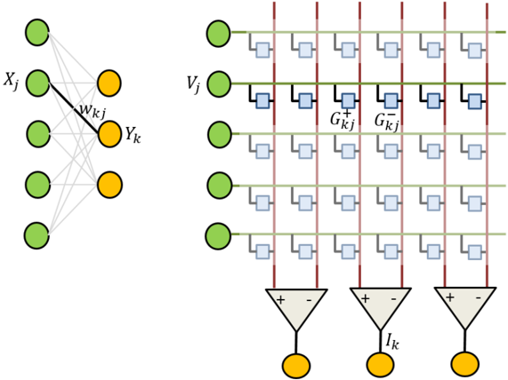
The image depicts a hybrid system combining a neural network architecture with an operational amplifier (op-amp) circuit. The left side illustrates a multi-layer perceptron (MLP) with weighted connections, while the right side shows a grid of op-amps with feedback gain stages and current outputs. The system appears to model signal processing or analog computation.
### Components/Axes
#### Left: Neural Network
- **Nodes**:
- **Green circles**: Input (`X_j`) and output (`Y_k`) nodes.
- **Orange circles**: Hidden layer nodes.
- **Connections**:
- **Gray lines**: General interconnections between nodes.
- **Black line**: Highlighted connection with weight `W_kj` between a hidden node and output node.
- **Labels**:
- `X_j`: Input vector.
- `Y_k`: Output vector.
- `W_kj`: Weight matrix between hidden layer `k` and output layer.
#### Right: Op-Amp Circuit
- **Grid Structure**:
- **Columns**: Labeled `V_j` (input voltages) at the top.
- **Rows**: Labeled `I_k` (output currents) at the bottom.
- **Blocks**:
- **Blue squares**: Gain stages labeled `G_kj^+` (positive feedback) and `G_kj^-` (negative feedback).
- **Red vertical lines**: Likely power supply rails or signal isolation barriers.
- **Green horizontal lines**: Ground or reference potentials.
- **Outputs**:
- **Yellow circles**: Labeled `I_k`, representing output currents.
- **Triangular symbols**: Summing junctions with `+` and `-` inputs, connected to `I_k`.
### Detailed Analysis
#### Neural Network
- The MLP has **5 input nodes** (`X_j`), **3 hidden layers** (orange nodes), and **1 output node** (`Y_k`).
- Weights (`W_kj`) are explicitly labeled on a single connection, suggesting a focus on specific synaptic strength.
- No activation functions are depicted, implying a linear model or abstraction.
#### Op-Amp Circuit
- **Symmetry**: Each column processes `V_j` through **4 gain stages** (2 positive, 2 negative feedback).
- **Gain Values**: `G_kj^+` and `G_kj^-` are identical in magnitude but opposite in polarity, indicating balanced feedback.
- **Current Outputs**: Three `I_k` currents are summed at the bottom, suggesting aggregation of processed signals.
### Key Observations
1. **Neural Network**:
- The highlighted `W_kj` weight implies criticality in the output computation.
- No bias terms are shown, simplifying the model.
2. **Op-Amp Circuit**:
- Red lines separate columns, possibly indicating independent processing paths.
- Green lines connect all `V_j` inputs to ground, ensuring a common reference.
3. **Integration**:
- The system bridges digital (neural network) and analog (op-amp) domains, possibly for hybrid computation.
### Interpretation
- **Neural Network**: Represents a simplified MLP for pattern recognition or classification, with emphasis on weight `W_kj` as a tunable parameter.
- **Op-Amp Grid**: Models a multi-stage amplifier with feedback control, where `G_kj^+` and `G_kj^-` stabilize gain while `I_k` outputs aggregate processed signals.
- **Hybrid System**: Suggests an analog implementation of neural network operations, where op-amp stages emulate synaptic weights (`W_kj`) and feedback loops. The `V_j` inputs could represent neuron activations, and `I_k` outputs mimic synaptic currents.
### Uncertainties
- Activation functions in the neural network are unspecified.
- Exact values for `G_kj^+`, `G_kj^-`, and `W_kj` are not provided.
- The purpose of red/green lines (power vs. signal) is inferred but not explicitly labeled.