## Flowchart: Human Hierarchy-Based Image Processing and Prediction System
### Overview
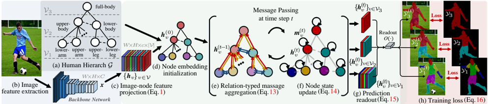
The diagram illustrates a multi-stage technical pipeline for human-centric image processing, combining hierarchical body part analysis, neural network operations, and graph-based message passing. It progresses from raw image input to prediction readout and training loss calculation, with explicit component labeling (a-h) and color-coded data flows.
### Components/Axes
1. **Human Hierarchy (a)**
- Labeled nodes: `full-body`, `upper-body`, `lower-body`, `upper-arm`, `lower-arm`, `upper-leg`, `lower-leg`
- Hierarchical structure: `V₃` (full-body) → `V₂` (upper/lower-body) → `V₁` (arm/leg parts)
2. **Image Feature Extraction (b)**
- Backbone network processes input image `x` (W×H×C dimensions)
- Output: Feature map `{h_v}` for nodes in hierarchy
3. **Image-Node Feature Projection (c)**
- Equation reference: `Eq.1`
- Projects image features to node embeddings `h_v^(0)`
4. **Node Embedding Initialization (d)**
- Initial node states `h_v^(0)` visualized as colored spheres (red, blue, green, purple)
5. **Message Passing (e)**
- Temporal steps: `h_v^(t-1)` → `m_v^(t)` → `h_v^(t)`
- Relation-typed aggregation: `Eq.13`
- Color-coded message flows (arrows) between nodes
6. **Node State Update (f)**
- Equation reference: `Eq.14`
- Updated node states `h_v^(t)` after message passing
7. **Prediction Readout (g)**
- Hierarchical readout: `O(·)` function applied to `h_v^(t)`
- Outputs `{h_v^(t)}` for `V₁`, `V₂`, `V₃`
8. **Training Loss (h)**
- Loss terms: `Loss₁` (V₁), `Loss₂` (V₂), `Loss₃` (V₃)
- Color-coded loss contributions (red, blue, green)
### Detailed Analysis
- **Color Coding**:
- Red: Upper-body/arm parts (`V₂`, `V₁` upper-arm)
- Blue: Lower-body/leg parts (`V₂`, `V₁` lower-leg)
- Green: Full-body (`V₃`)
- Purple: Intermediate node states
- **Data Flow**:
1. Image → Backbone Network (b) → Node embeddings (c,d)
2. Message passing (e,f) refines embeddings across time steps
3. Readout (g) produces hierarchical predictions
4. Loss (h) aggregates errors across body parts
- **Equations**:
- `Eq.1`: Image-node projection mechanism
- `Eq.13`: Relation-typed message aggregation
- `Eq.14`: Node state update rule
- `Eq.15`: Prediction readout formulation
- `Eq.16`: Total training loss composition
### Key Observations
1. **Hierarchical Processing**:
- Body parts are organized in a three-tier hierarchy (V₁→V₂→V₃), enabling multi-scale feature learning.
2. **Graph Neural Network (GNN) Integration**:
- Message passing (e,f) suggests a GNN architecture where nodes (body parts) interact via relation-aware updates.
3. **Multi-Task Loss**:
- Separate losses for arm/leg/body parts indicate a multi-task learning objective, balancing granular and holistic predictions.
4. **Temporal Dynamics**:
- Time-step notation (`h_v^(t)`) implies sequential processing, possibly for video or dynamic pose estimation.
### Interpretation
This system combines **human-centric hierarchy** with **graph neural networks** to model body part relationships. The message passing mechanism (e,f) allows contextual refinement of node states, while the hierarchical readout (g) ensures predictions at multiple granularities. The multi-task loss (h) suggests optimization for both detailed (V₁) and global (V₃) accuracy. The color coding visually reinforces the hierarchical structure and data flow, though explicit legend labels are absent. The architecture likely addresses challenges in pose estimation by leveraging both spatial hierarchy and temporal dynamics.