## Diagram: Decode-only LLM and Transformer Block
### Overview
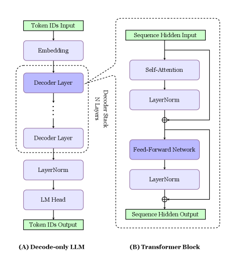
The image presents two diagrams side-by-side. Diagram (A) illustrates the architecture of a Decode-only LLM (Language Model), while diagram (B) depicts the structure of a Transformer Block. Both diagrams use a top-down flow to represent the processing steps.
### Components/Axes
**Diagram (A): Decode-only LLM**
* **Input:** Token IDs Input (Green box at the top)
* **Layers:**
* Embedding (Blue box)
* Decoder Layer (Blue box, repeated N times within a dashed box labeled "Decoder Stack N Layers")
* LayerNorm (Blue box)
* LM Head (Blue box)
* **Output:** Token IDs Output (Green box at the bottom)
* **Label:** (A) Decode-only LLM (bottom-left)
**Diagram (B): Transformer Block**
* **Input:** Sequence Hidden Input (Green box at the top)
* **Layers:**
* Self-Attention (Blue box)
* LayerNorm (Blue box)
* Feed-Forward Network (Blue box)
* LayerNorm (Blue box)
* **Connections:**
* A direct connection (arrow) bypasses the Self-Attention and LayerNorm layers, adding to the output of the first LayerNorm.
* A direct connection (arrow) bypasses the Feed-Forward Network and LayerNorm layers, adding to the output of the second LayerNorm.
* **Output:** Sequence Hidden Output (Green box at the bottom)
* **Label:** (B) Transformer Block (bottom-right)
### Detailed Analysis
**Diagram (A): Decode-only LLM**
1. **Token IDs Input:** The process begins with inputting token IDs.
2. **Embedding:** The token IDs are then passed through an embedding layer.
3. **Decoder Stack:** The core of the model consists of N Decoder Layers. The exact number of layers is not specified, but it is represented by "N Layers".
4. **LayerNorm:** A Layer Normalization layer follows the decoder stack.
5. **LM Head:** The output is then fed into a Language Model Head.
6. **Token IDs Output:** Finally, the model outputs token IDs.
**Diagram (B): Transformer Block**
1. **Sequence Hidden Input:** The block receives a sequence of hidden states as input.
2. **Self-Attention:** The input is processed through a self-attention mechanism.
3. **LayerNorm:** The output of the self-attention is normalized using LayerNorm. A residual connection adds the original input to the output of this LayerNorm.
4. **Feed-Forward Network:** The result is then passed through a feed-forward network.
5. **LayerNorm:** Another LayerNorm layer normalizes the output of the feed-forward network. A residual connection adds the input of the feed-forward network to the output of this LayerNorm.
6. **Sequence Hidden Output:** The block outputs a sequence of hidden states.
### Key Observations
* Diagram (A) shows a sequential flow of data through the layers of a Decode-only LLM.
* Diagram (B) highlights the internal structure of a Transformer Block, emphasizing the self-attention mechanism, feed-forward network, and residual connections.
* Both diagrams use similar visual elements (boxes, arrows) to represent layers and data flow.
* The "Decoder Stack N Layers" in diagram (A) indicates that the Decoder Layer is repeated multiple times, a key characteristic of deep learning models.
* The residual connections in diagram (B) are crucial for training deep networks, as they help to mitigate the vanishing gradient problem.
### Interpretation
The diagrams illustrate the architecture of a Decode-only LLM and the internal structure of a Transformer Block, which are fundamental components in modern natural language processing models. The Decode-only LLM processes input tokens through a series of embedding, decoding, and normalization layers, culminating in the generation of output tokens. The Transformer Block, with its self-attention mechanism and feed-forward network, enables the model to capture complex relationships between words in a sequence. The residual connections in the Transformer Block are essential for training deep networks effectively. The diagrams highlight the modularity and hierarchical structure of these models, where individual blocks can be stacked to create more complex architectures.