## Diagram: Architecture of a Decode-only Large Language Model (LLM) and its Transformer Block
### Overview
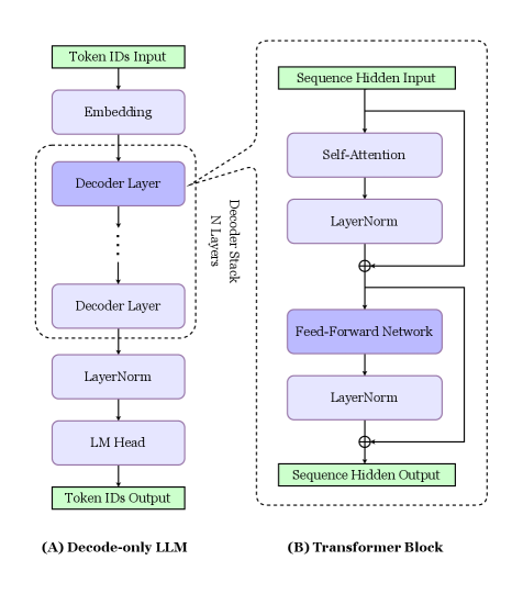
The image is a technical diagram illustrating the high-level architecture of a decode-only Large Language Model (LLM) and a detailed breakdown of its core component, the Transformer Block. It is divided into two main sections: (A) on the left, showing the full model pipeline, and (B) on the right, providing an expanded view of a single decoder layer. The diagram uses colored boxes (green for inputs/outputs, purple for processing layers) and directional arrows to depict data flow.
### Components/Axes
The diagram is composed of two primary, labeled sections:
**Section (A) Decode-only LLM (Left Side):**
* **Input:** A green box labeled "Token IDs Input" at the top.
* **Processing Pipeline (top to bottom):**
1. "Embedding" (purple box)
2. A dashed box labeled "Decoder Stack" containing "N Layers" of "Decoder Layer" (purple boxes). An ellipsis (...) indicates repetition.
3. "LayerNorm" (purple box)
4. "LM Head" (purple box)
* **Output:** A green box labeled "Token IDs Output" at the bottom.
**Section (B) Transformer Block (Right Side):**
* **Input:** A green box labeled "Sequence Hidden Input" at the top.
* **Processing Pipeline (top to bottom):**
1. "Self-Attention" (purple box)
2. "LayerNorm" (purple box)
3. A circle with a plus sign (⊕) indicating a residual (skip) connection.
4. "Feed-Forward Network" (purple box)
5. "LayerNorm" (purple box)
6. Another residual connection (⊕).
* **Output:** A green box labeled "Sequence Hidden Output" at the bottom.
* **Flow Indicators:** Arrows show the main sequential path and the residual connections that bypass the Self-Attention and Feed-Forward Network blocks.
**Spatial Relationship:** A dashed line connects the "Decoder Layer" box in Section (A) to the entire expanded diagram of Section (B), explicitly indicating that (B) is a detailed view of one layer within the stack shown in (A).
### Detailed Analysis
The diagram details the sequential data transformation process in a decode-only LLM:
1. **Input Processing:** The model receives "Token IDs Input." These IDs are first passed through an "Embedding" layer, which converts discrete token IDs into continuous vector representations.
2. **Core Processing (Decoder Stack):** The embedded vectors enter a stack of "N" identical "Decoder Layer" modules. The diagram shows the first and last layer with an ellipsis in between, signifying repetition.
3. **Final Processing:** After the final decoder layer, the output passes through a "LayerNorm" (Layer Normalization) layer and then an "LM Head" (Language Model Head), which projects the hidden states back into the vocabulary space to produce logits for the next token prediction.
4. **Output:** The final output is "Token IDs Output," representing the predicted next token(s).
The expanded view of a single **Transformer Block (Decoder Layer)** reveals its internal structure:
* The "Sequence Hidden Input" first undergoes "Self-Attention," allowing the model to weigh the importance of different positions in the input sequence.
* The output of the attention mechanism is normalized via "LayerNorm" and then added to the original input via a residual connection (⊕).
* This combined signal is then processed by a "Feed-Forward Network," typically consisting of two linear transformations with a non-linear activation function.
* The output of the feed-forward network is again normalized and added to its input via a second residual connection (⊕), resulting in the "Sequence Hidden Output" for that layer.
### Key Observations
* **Architectural Clarity:** The diagram clearly distinguishes between the macro-architecture (the full model pipeline) and the micro-architecture (the internal structure of a single layer).
* **Residual Connections:** The use of the ⊕ symbol explicitly highlights the critical role of residual (skip) connections in the Transformer block, which help mitigate the vanishing gradient problem in deep networks.
* **Layer Normalization Placement:** "LayerNorm" is applied both within each Transformer block (after attention and feed-forward networks) and once after the entire decoder stack, which is a specific design choice in this architecture.
* **Decode-Only Nature:** The title "(A) Decode-only LLM" and the unidirectional flow (no encoder shown) confirm this is an autoregressive model designed for tasks like text generation, where each token is predicted based only on previous tokens.
### Interpretation
This diagram serves as a foundational schematic for understanding the data flow and component hierarchy in modern autoregressive language models like GPT (Generative Pre-trained Transformer).
* **What it demonstrates:** It visually explains how a sequence of input tokens is transformed step-by-step into a prediction for the next token. The core computational work happens in the repeated Transformer blocks, which use self-attention to build contextual representations of the input sequence.
* **Relationship between elements:** Section (B) is the fundamental building block of Section (A). The performance and capability of the entire LLM in (A) are directly determined by the number ("N") and the internal design of the Transformer blocks shown in (B). The residual connections and layer normalization are crucial for enabling the training of very deep stacks of these blocks.
* **Notable design choice:** The placement of "LayerNorm" *after* the attention and feed-forward sub-layers (a "post-norm" configuration) is one of several possible variants. This choice can impact model stability and training dynamics compared to placing normalization *before* the sub-layers ("pre-norm").
* **Underlying principle:** The diagram encapsulates the core principle of the Transformer architecture: replacing recurrence (like in RNNs) with parallelizable self-attention mechanisms, allowing for more efficient training on long sequences. The "LM Head" at the end ties the model's rich internal representations back to the concrete task of next-token prediction.