\n
## Diagram: System Architecture/Flow
### Overview
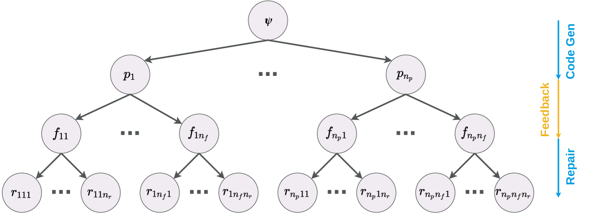
The image depicts a hierarchical diagram representing a system or process flow. It appears to illustrate a feedback loop involving code generation, feedback, and repair, culminating in a central element denoted by the Greek letter psi (ψ). The diagram is structured as a tree, with branching nodes and terminal elements.
### Components/Axes
The diagram consists of the following components:
* **ψ (Psi):** A central node at the top of the diagram.
* **p₁ ... p<sub>np</sub>:** Intermediate nodes branching from ψ. The subscript 'np' indicates a variable number of these nodes.
* **f<sub>11</sub> ... f<sub>nf</sub>:** Intermediate nodes branching from the 'p' nodes. The subscripts '11' through 'nf' indicate a variable number of these nodes.
* **r<sub>111</sub> ... r<sub>npnf</sub>:** Terminal nodes branching from the 'f' nodes. The subscripts '111' through 'npnf' indicate a variable number of these nodes.
* **Labels:** "Code Gen" (blue), "Feedback" (yellow), "Repair" (purple). These labels are positioned along the right side of the diagram, indicating the flow direction.
### Detailed Analysis or Content Details
The diagram shows a tree-like structure originating from the central node ψ.
* From ψ, there are 'np' branches, each leading to a node labeled p<sub>i</sub>, where 'i' ranges from 1 to np.
* Each p<sub>i</sub> node then branches into 'nf' nodes labeled f<sub>ij</sub>, where 'i' ranges from 1 to np and 'j' ranges from 1 to nf.
* Finally, each f<sub>ij</sub> node branches into a variable number of terminal nodes labeled r<sub>ijk</sub>, where 'i' ranges from 1 to np, 'j' ranges from 1 to nf, and 'k' ranges from 1 to some unspecified number. The notation suggests that the number of terminal nodes can vary for each f<sub>ij</sub> node.
* The right side of the diagram has three labels: "Code Gen" (blue), "Feedback" (yellow), and "Repair" (purple). These labels are connected to the diagram via lines, indicating the direction of flow. The lines are positioned vertically, suggesting a sequential process.
### Key Observations
The diagram illustrates a hierarchical decomposition of a process. The central node ψ likely represents the overall goal or system. The 'p' nodes could represent planning or problem definition stages. The 'f' nodes might represent function or feature implementation, and the 'r' nodes could represent the resulting outputs or results. The labels "Code Gen", "Feedback", and "Repair" suggest an iterative process where code is generated, feedback is received, and repairs are made.
### Interpretation
This diagram likely represents a system for automated code generation and refinement. The central node ψ could represent the desired software or system. The process begins with planning (p nodes), followed by function implementation (f nodes), and finally, the generation of results (r nodes). The "Code Gen" label indicates that code is generated at some point in this process. The "Feedback" label suggests that the generated code is evaluated, and feedback is provided. The "Repair" label indicates that the code is modified based on the feedback. This cycle of code generation, feedback, and repair is repeated iteratively, potentially improving the quality and functionality of the generated code. The variable number of nodes at each level (np, nf, and the number of 'r' nodes) suggests that the process is flexible and can adapt to different problem complexities. The diagram is a high-level representation and does not provide specific details about the algorithms or techniques used in each stage.