\n
## Hierarchical Tree Diagram with Process Flow
### Overview
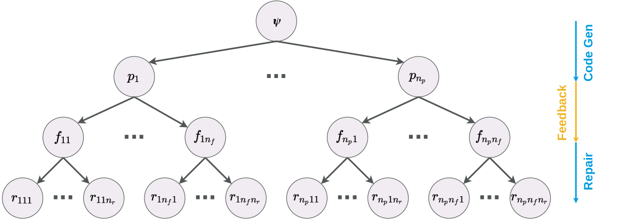
The image displays a four-level hierarchical tree diagram with a root node at the top, branching downward into multiple child nodes. To the right of the tree, a vertical, three-stage process flow is depicted with directional arrows. The diagram uses a consistent visual language: circular nodes with a light purple fill and dark gray outlines, connected by dark gray directional arrows. The overall structure suggests a decomposition of a high-level concept or task into progressively more specific components or instances.
### Components/Axes
**Tree Structure:**
* **Root Node (Top Center):** A single node labeled with the Greek letter **ψ** (psi).
* **First Level (Below ψ):** Nodes labeled **p₁** through **p_{n_p}**. An ellipsis (**...**) between p₁ and p_{n_p} indicates multiple nodes at this level.
* **Second Level (Below each p node):** Each p node branches into nodes labeled with **f** and double subscripts. For example, under p₁ are nodes **f₁₁** through **f_{1n_f}** (with an ellipsis between). Similarly, under p_{n_p} are nodes **f_{n_p1}** through **f_{n_p n_f}**.
* **Third/Leaf Level (Bottom):** Each f node branches into nodes labeled with **r** and triple subscripts. For example, under f₁₁ are nodes **r₁₁₁** through **r_{11n_r}** (with an ellipsis). This pattern continues for all f nodes, ending with nodes like **r_{n_p n_f 1}** through **r_{n_p n_f n_r}**.
**Process Flow (Right Side):**
* A vertical sequence of three text labels connected by downward-pointing arrows.
* **Top Label:** **Code Gen** (in blue text).
* **Middle Label:** **Feedback** (in orange text).
* **Bottom Label:** **Repair** (in blue text).
* A blue arrow points from "Code Gen" down to "Feedback". An orange arrow points from "Feedback" down to "Repair".
### Detailed Analysis
**Node Hierarchy and Indexing:**
The tree follows a strict, nested indexing scheme:
1. **Level 1 (p nodes):** Indexed by a single variable `p`, from 1 to `n_p`.
2. **Level 2 (f nodes):** Indexed by two variables. The first index corresponds to the parent p node (e.g., `1` for children of p₁, `n_p` for children of p_{n_p}). The second index runs from 1 to `n_f` for each parent.
3. **Level 3 (r nodes):** Indexed by three variables. The first two indices correspond to the parent f node (e.g., `1,1` for children of f₁₁, `n_p, n_f` for children of f_{n_p n_f}). The third index runs from 1 to `n_r` for each parent.
**Spatial Relationships:**
* The tree is centered in the main area of the image.
* The process flow is positioned to the far right, vertically aligned with the middle to lower portion of the tree.
* All arrows in the tree point downward, indicating a parent-to-child or decomposition relationship.
* The arrows in the side flow also point downward, indicating a sequential process.
### Key Observations
1. **Uniform Structure:** The branching factor is consistent at each level for all sub-trees. Every p node has `n_f` children, and every f node has `n_r` children.
2. **Ellipses for Abstraction:** The use of ellipses (`...`) at each level is a critical notational element, explicitly indicating that the diagram shows a generalized template rather than a specific instance with fixed numbers of nodes.
3. **Color-Coded Process Flow:** The "Feedback" stage and its incoming/outgoing arrows are highlighted in orange, distinguishing it from the blue "Code Gen" and "Repair" stages. This visually emphasizes the feedback loop as a distinct, central phase.
4. **Disconnected Flows:** The hierarchical tree and the vertical process flow are not connected by any lines or arrows in the diagram. Their relationship is implied by proximity and context.
### Interpretation
This diagram illustrates a **generalized model for a hierarchical problem-solving or generation process**, likely within a computational or engineering context (e.g., software engineering, automated planning, or machine learning).
* **The Tree (ψ → p → f → r):** Represents the **decomposition of a high-level goal or specification (ψ)** into manageable sub-problems or components (`p`), which are further broken down into specific functions or features (`f`), and finally into concrete results, requirements, or repair actions (`r`). The triple-index `r_{ijk}` suggests a highly granular, traceable mapping from the root to the most specific elements.
* **The Side Flow (Code Gen → Feedback → Repair):** Represents an **iterative execution or refinement cycle**. A process generates code or a solution ("Code Gen"), evaluates it ("Feedback"), and then makes corrections ("Repair").
* **Synthesized Meaning:** The most plausible interpretation is that the tree defines the **structure or search space** of a problem, while the side flow describes the **operational process** applied to elements within that structure. For instance, one might generate code (`Code Gen`) for a specific function `f_{ij}`, receive test results or user input (`Feedback`), and then debug or modify that specific function (`Repair`). The model is abstract and scalable, as denoted by the variables `n_p`, `n_f`, and `n_r`. The use of Greek letter ψ for the root often signifies a program, specification, or overall state in formal methods.