## Hierarchical System Architecture Diagram: Code Generation and Feedback Flow
### Overview
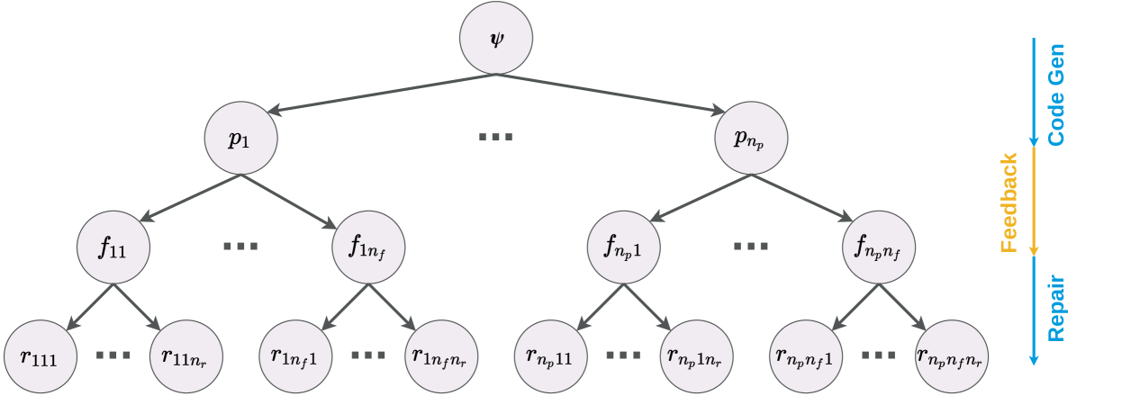
The diagram illustrates a multi-level hierarchical system architecture with feedback loops and code generation/repair processes. It features a root node (ψ) branching into primary nodes (p₁ to pₙ), which further decompose into functional nodes (f₁₁, f₁ₙ, ..., fₙ₁, fₙₙ), each containing response nodes (r₁₁₁, r₁₁ₙ, ..., rₙₙ₁, rₙₙₙ). Feedback arrows connect response nodes back to their parent functional nodes, while a separate code generation/repair flow operates alongside the hierarchy.
### Components/Axes
1. **Root Node**: ψ (topmost node)
2. **Primary Nodes**: p₁, p₂, ..., pₙ (directly connected to ψ)
3. **Functional Nodes**:
- f₁₁, f₁ₙ (under p₁)
- fₙ₁, fₙₙ (under pₙ)
4. **Response Nodes**:
- r₁₁₁, r₁₁ₙ (under f₁₁)
- rₙ₁₁, rₙₙₙ (under fₙₙ)
5. **Flow Arrows**:
- **Feedback**: Orange arrows from r-nodes to f-nodes
- **Code Generation/Repair**: Blue arrows from f-nodes to a separate process
### Detailed Analysis
- **Hierarchical Structure**:
- ψ → p₁ → f₁₁ → [r₁₁₁, r₁₁ₙ]
- ψ → p₁ → f₁ₙ → [r₁ₙ₁, r₁ₙₙ]
- ψ → pₙ → fₙ₁ → [rₙ₁₁, rₙ₁ₙ]
- ψ → pₙ → fₙₙ → [rₙₙ₁, rₙₙₙ]
- **Feedback Mechanism**:
- Response nodes (r) feed back to their parent functional nodes (f) via orange arrows
- **Code Generation/Repair Flow**:
- Functional nodes (f) connect to a separate process via blue arrows labeled "Code Gen" and "Repair"
### Key Observations
1. **Modular Decomposition**:
- Primary nodes (p) split into functional nodes (f) with distinct response nodes (r)
- Each f-node contains 2-4 r-nodes (e.g., f₁₁ has r₁₁₁ and r₁₁ₙ)
2. **Feedback Loops**:
- All r-nodes have feedback connections to their parent f-nodes
- Feedback arrows are consistently orange and positioned below the hierarchy
3. **Code Generation/Repair**:
- Blue arrows originate from f-nodes but lack explicit termination points
- Positioned to the right of the main hierarchy
### Interpretation
This diagram represents a **modular system architecture** with three key characteristics:
1. **Hierarchical Processing**:
- ψ represents the system's root, with p-nodes acting as intermediate processors
- Functional nodes (f) handle specific tasks, each generating multiple response nodes (r)
2. **Iterative Refinement**:
- Feedback loops from r-nodes to f-nodes suggest error correction or performance optimization
- The orange feedback arrows imply real-time adjustments to functional node operations
3. **Code-Centric Workflow**:
- The blue "Code Gen/Repair" flow indicates a separate code management system
- Functional nodes likely interface with this system for code generation and error repair
**Notable Patterns**:
- Symmetrical structure in p₁/pₙ and f₁₁/fₙₙ nodes suggests parallel processing capabilities
- Absence of numerical values implies this is a conceptual architecture rather than a data-driven model
- Feedback loops outnumber code generation/repair arrows 4:1, emphasizing real-time adjustment over code management
**Technical Implications**:
- The architecture could model a code generation pipeline with automated feedback for quality assurance
- Response nodes (r) might represent test cases or validation metrics
- The dual flow system (feedback vs. code management) suggests separation of concerns between operational adjustments and code-level modifications