\n
## Diagram: Splice and Loop Operations on Tangled Lines
### Overview
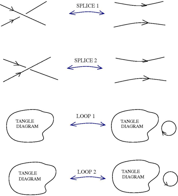
The image depicts a series of diagrams illustrating operations on tangled lines, specifically "Splice" and "Loop" operations. Each operation takes a configuration of intersecting lines (a "Tangle Diagram") as input and transforms it into a different configuration of lines. The diagrams are arranged in two rows, with "Splice" operations in the top row and "Loop" operations in the bottom row.
### Components/Axes
The diagram consists of the following components:
* **Tangle Diagrams:** Irregularly shaped blobs labeled "TANGLE DIAGRAM" representing configurations of intersecting lines.
* **Lines:** Straight lines with arrowheads indicating direction.
* **Labels:** Text labels indicating the operation being performed ("SPLICE 1", "SPLICE 2", "LOOP 1", "LOOP 2").
* **Arrows:** Bidirectional arrows connecting the input and output tangle diagrams, indicating the transformation.
* **Circles:** Small circles on the right side of the bottom two diagrams.
### Detailed Analysis or Content Details
The diagram is structured into four distinct transformations:
1. **SPLICE 1:**
* Input: A tangle diagram with two lines crossing each other. Both lines have arrowheads pointing towards the intersection.
* Transformation: Indicated by a bidirectional arrow labeled "SPLICE 1".
* Output: A tangle diagram with two parallel lines, both with arrowheads pointing in the same direction.
2. **SPLICE 2:**
* Input: A tangle diagram with two lines crossing each other. Both lines have arrowheads pointing towards the intersection.
* Transformation: Indicated by a bidirectional arrow labeled "SPLICE 2".
* Output: A tangle diagram with two parallel lines, both with arrowheads pointing in the same direction.
3. **LOOP 1:**
* Input: A tangle diagram with two lines crossing each other. Both lines have arrowheads pointing towards the intersection.
* Transformation: Indicated by a bidirectional arrow labeled "LOOP 1".
* Output: A tangle diagram with two lines, and a small circle on the right.
4. **LOOP 2:**
* Input: A tangle diagram with two lines crossing each other. Both lines have arrowheads pointing towards the intersection.
* Transformation: Indicated by a bidirectional arrow labeled "LOOP 2".
* Output: A tangle diagram with two lines, and a small circle on the right.
### Key Observations
* The "Splice" operations appear to untangle the lines, resulting in parallel lines.
* The "Loop" operations also start with a tangle diagram, but the output includes a small circle, suggesting the creation of a closed loop.
* The input tangle diagrams are identical for all four operations.
* The outputs of "SPLICE 1" and "SPLICE 2" are identical.
* The outputs of "LOOP 1" and "LOOP 2" are identical.
### Interpretation
The diagram illustrates two distinct operations – "Splice" and "Loop" – that can be applied to tangled line configurations. The "Splice" operation seems to resolve the tangle by aligning the lines, while the "Loop" operation introduces a circular element. The fact that the input is the same for all operations, and that SPLICE 1 and 2, and LOOP 1 and 2 produce the same outputs, suggests that these operations might be deterministic, or that the diagram is only showing one possible outcome for each operation. The small circles in the "Loop" diagrams likely represent a closed loop or a change in the topological structure of the lines. This could be a visual representation of mathematical concepts related to knot theory or braid groups, where "splices" and "loops" are fundamental operations. The diagram doesn't provide quantitative data, but rather a qualitative illustration of transformations.