\n
## Diagram: Code Model Feedback Loop
### Overview
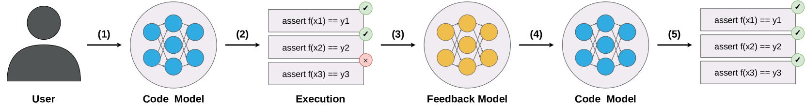
The image depicts a diagram illustrating a feedback loop in a code model, likely related to testing or refinement of code generation. It shows a process starting with a user input, moving through code generation, execution with assertions, feedback based on assertion results, and finally, an updated code model. The diagram uses stylized representations of a user, code models (as node networks), execution results, and feedback mechanisms.
### Components/Axes
The diagram is segmented into five stages, labeled (1) through (5) with arrows indicating the flow of information. The stages are:
1. **User:** Represented by a silhouette of a person.
2. **Code Model:** Depicted as a network of interconnected nodes, colored blue and yellow.
3. **Execution:** Shows three assertion statements: `assert f(x1) == y1`, `assert f(x2) == y2`, `assert f(x3) == y3`. Two assertions pass (green checkmarks) and one fails (red 'x').
4. **Feedback Model:** Similar to the Code Model, but with a different arrangement of nodes, also colored blue and yellow.
5. **Code Model:** An updated version of the Code Model, represented as a rectangular block containing the three assertion statements, all marked with green checkmarks.
### Detailed Analysis or Content Details
* **Stage 1 (User):** A simple silhouette of a person, indicating the source of the initial input.
* **Stage 2 (Code Model):** A network of approximately 12 nodes, with roughly half colored blue and half colored yellow. The nodes are interconnected by lines.
* **Stage 3 (Execution):** Three assertion statements are presented:
* `assert f(x1) == y1` - Passes (green checkmark)
* `assert f(x2) == y2` - Passes (green checkmark)
* `assert f(x3) == y3` - Fails (red 'x')
* **Stage 4 (Feedback Model):** A network of approximately 12 nodes, with roughly half colored blue and half colored yellow. The arrangement of nodes is different from the initial Code Model.
* **Stage 5 (Code Model):** A rectangular block containing the three assertion statements:
* `assert f(x1) == y1` - Passes (green checkmark)
* `assert f(x2) == y2` - Passes (green checkmark)
* `assert f(x3) == y3` - Passes (green checkmark)
### Key Observations
The diagram highlights a process of iterative refinement. The initial code model fails one of the assertions during execution. This failure triggers a feedback mechanism (represented by the Feedback Model), which results in an updated code model that passes all assertions. The color scheme (blue and yellow) is consistent across the Code Model and Feedback Model stages, suggesting these colors represent different components or aspects of the model.
### Interpretation
This diagram illustrates a core concept in machine learning and software development: the iterative refinement of a model based on feedback. The user provides an initial input, which is translated into a code model. The execution phase tests the code model against a set of assertions. When an assertion fails, the feedback model uses this information to adjust the code model, aiming to improve its performance and correctness. The final stage shows a successful code model, indicating that the feedback loop has converged on a solution that satisfies all assertions.
The diagram suggests a system where code is generated, tested, and refined automatically. The use of assertions implies a formal verification process. The visual representation of the code model as a network of nodes could represent a neural network or a similar complex system. The diagram is a high-level overview and doesn't provide details about the specific algorithms or techniques used in the feedback loop. However, it effectively communicates the fundamental principle of iterative improvement through testing and refinement. The consistent use of blue and yellow nodes suggests that these colors represent different types of components within the code model, and the feedback mechanism adjusts the connections or properties of these components to achieve the desired behavior.