## Neural Network Diagram: Error Removal and Abduction
### Overview
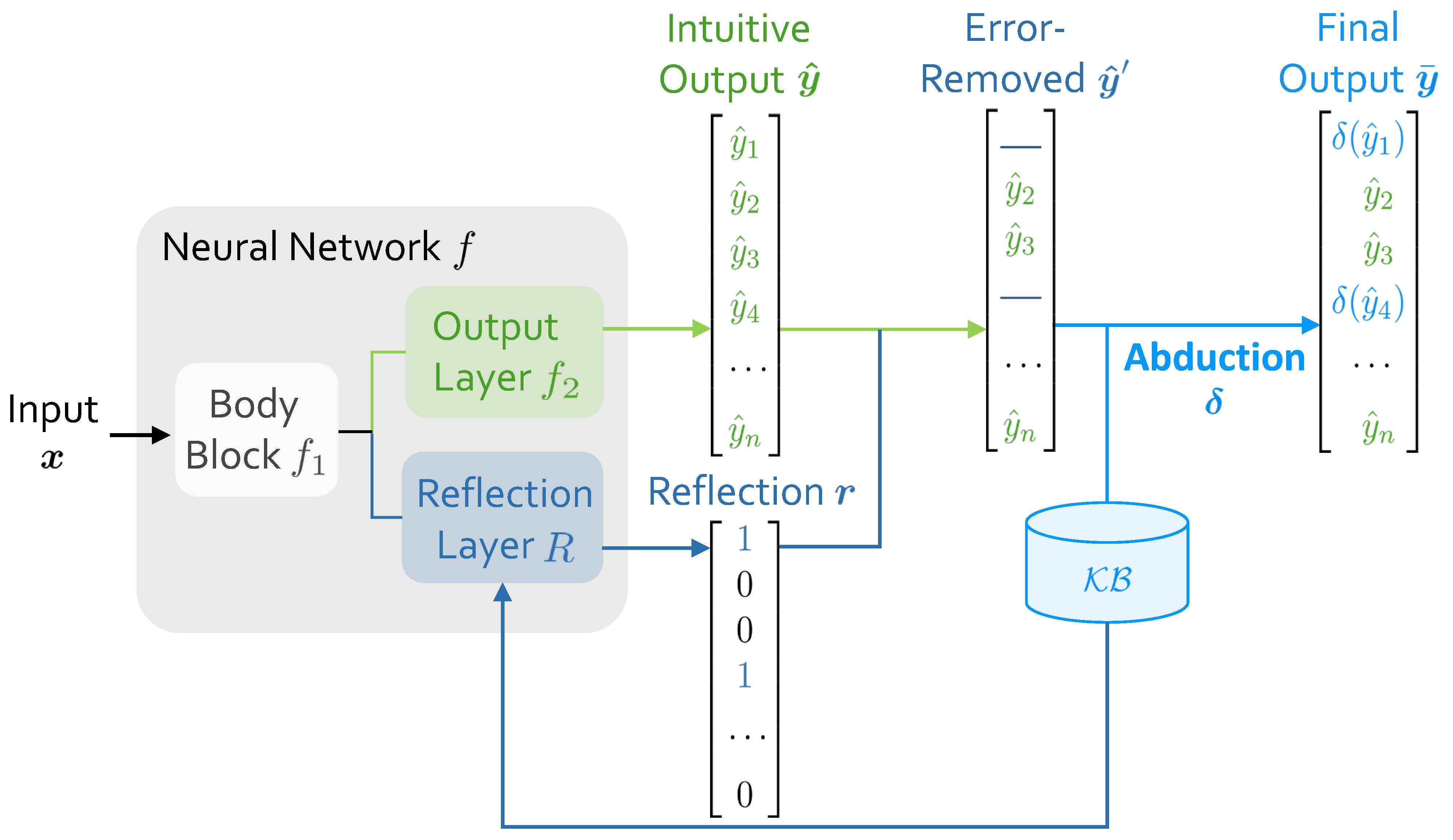
The image is a diagram illustrating a neural network architecture with error removal and abduction processes. It shows the flow of data from input to final output, highlighting the steps of intuitive output, error removal, and abduction using a knowledge base (KB).
### Components/Axes
* **Neural Network f:** A gray rounded rectangle containing the "Body Block f1" and "Output Layer f2" (green) and "Reflection Layer R" (blue).
* **Input x:** An arrow pointing into the "Body Block f1" of the neural network.
* **Intuitive Output ŷ:** A green column vector labeled with ŷ, containing elements ŷ1, ŷ2, ŷ3, ŷ4, ..., ŷn.
* **Error-Removed ŷ':** A column vector labeled with ŷ', containing elements with some values removed (represented by horizontal lines), ŷ2, ŷ3, ..., ŷn.
* **Final Output ȳ:** A blue column vector labeled with ȳ, containing elements δ(ŷ1), ŷ2, ŷ3, δ(ŷ4), ..., ŷn.
* **Reflection Layer R:** A blue rounded rectangle within the Neural Network.
* **Reflection r:** A blue column vector containing binary values 1, 0, 0, 1, ..., 0.
* **Abduction δ:** A blue text label with an arrow pointing from the Error-Removed ŷ' column to the Final Output ȳ column.
* **KB:** A blue cylinder representing a knowledge base.
### Detailed Analysis
1. **Input:** The input *x* enters the Neural Network *f*.
2. **Body Block f1:** The input first goes through the "Body Block f1".
3. **Output Layer f2:** The output of the "Body Block f1" goes to the "Output Layer f2", which produces the "Intuitive Output ŷ".
4. **Intuitive Output ŷ:** The "Intuitive Output ŷ" is a column vector [ŷ1, ŷ2, ŷ3, ŷ4, ..., ŷn].
5. **Reflection Layer R:** The "Reflection Layer R" receives input from the "Body Block f1" and produces "Reflection r".
6. **Reflection r:** The "Reflection r" is a column vector [1, 0, 0, 1, ..., 0].
7. **Error-Removed ŷ':** The "Intuitive Output ŷ" is processed to remove errors, resulting in "Error-Removed ŷ'". Some elements are removed (represented by horizontal lines). The remaining elements are ŷ2, ŷ3, ..., ŷn.
8. **Abduction δ:** The "Error-Removed ŷ'" is then processed using "Abduction δ" with information from the "KB" (Knowledge Base).
9. **Final Output ȳ:** The "Abduction δ" process results in the "Final Output ȳ", which is a column vector [δ(ŷ1), ŷ2, ŷ3, δ(ŷ4), ..., ŷn].
### Key Observations
* The diagram illustrates a neural network architecture that incorporates error removal and abduction.
* The "Intuitive Output ŷ" is refined by removing errors and applying abduction using a knowledge base.
* The "Reflection Layer R" and "Reflection r" seem to play a role in the error removal or abduction process, potentially providing feedback or context.
* The "Abduction δ" process appears to selectively modify elements of the "Error-Removed ŷ'" based on the knowledge base.
### Interpretation
The diagram presents a neural network model that aims to improve the quality of its output by incorporating error removal and abduction. The "Intuitive Output ŷ" is initially generated by the network, but it may contain errors or inconsistencies. The "Error-Removed ŷ'" step filters out some of these errors, and the "Abduction δ" step uses a knowledge base to refine the output further. The "Reflection Layer R" and "Reflection r" likely provide additional information or constraints to guide the error removal and abduction processes. This architecture suggests a system that combines data-driven learning with knowledge-based reasoning to produce more accurate and reliable results. The specific nature of the error removal and abduction processes would depend on the details of the implementation and the content of the knowledge base.