# Technical Diagram Analysis
## Diagram Structure
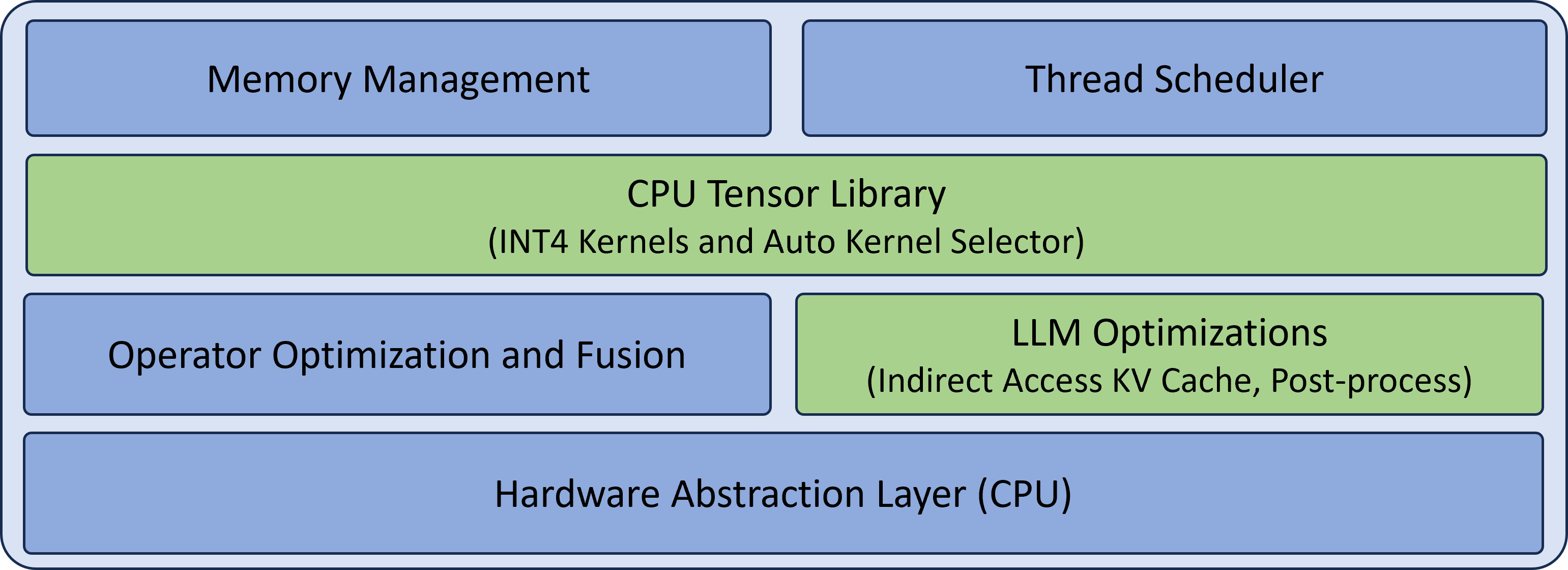
The image depicts a layered architecture diagram with six distinct components arranged vertically. The diagram uses two primary colors:
- **Blue** for core system components
- **Green** for optimization layers
## Component Breakdown
### Top Layer (Blue)
1. **Memory Management**
- Position: Top-left quadrant
- Function: Likely handles memory allocation/deallocation for tensor operations
2. **Thread Scheduler**
- Position: Top-right quadrant
- Function: Manages parallel execution of tensor operations
### Middle Layer (Green)
3. **CPU Tensor Library**
- Position: Full-width horizontal bar
- Sub-components:
- INT4 Kernels
- Auto Kernel Selector
- Function: Core tensor computation layer with quantization support
### Middle-Right Layer (Blue)
4. **Operator Optimization and Fusion**
- Position: Bottom-left quadrant
- Function: Combines multiple operations into single kernel executions
### Middle-Left Layer (Green)
5. **LLM Optimizations**
- Position: Bottom-right quadrant
- Sub-components:
- Indirect Access KV Cache
- Post-process
- Function: Specialized optimizations for large language models
### Bottom Layer (Blue)
6. **Hardware Abstraction Layer (CPU)**
- Position: Full-width bottom bar
- Function: Provides CPU-specific interface for tensor operations
## Spatial Relationships
- The CPU Tensor Library acts as the central processing unit
- Optimization layers (green) flank the core library
- Hardware abstraction layer provides foundational interface
- Memory and thread management components form the top control layer
## Technical Implications
This architecture suggests a multi-layered optimization strategy for CPU-based tensor operations, with specific enhancements for:
1. Quantized computations (INT4)
2. Large language model inference
3. Memory efficiency through operator fusion
4. Parallel execution management
The diagram emphasizes both hardware-level optimizations and algorithmic improvements for efficient tensor processing on CPU architectures.