# Technical Document Extraction: Flowchart Analysis
## Diagram Description
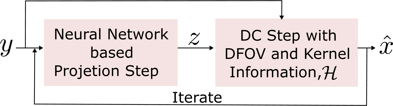
The image depicts a **two-component iterative process** represented as a flowchart. The diagram uses rectangular blocks to denote computational steps and arrows to indicate data flow. All text is in **English**.
---
### Component Breakdown
#### 1. Neural Network based Projection Step
- **Label**: "Neural Network based Projection Step"
- **Input**: Variable `y` (arrow pointing from `y` to the block)
- **Output**: Variable `z` (arrow pointing from the block to `z`)
- **Spatial Position**: Leftmost block in the diagram
#### 2. DC Step with DFOV and Kernel Information
- **Label**: "DC Step with DFOV and Kernel Information, H"
- **Input**: Variable `z` (arrow pointing from `z` to the block)
- **Output**: Variable `x̂` (arrow pointing from the block to `x̂`)
- **Spatial Position**: Rightmost block in the diagram
#### 3. Iteration Mechanism
- **Label**: "Iterate"
- **Function**: Feedback loop from `x̂` back to `y`
- **Spatial Position**: Arrows connecting `x̂` → `y`
---
### Variable Flow
1. **Initial Input**: `y` → Neural Network Projection Step → `z`
2. **Intermediate Processing**: `z` → DC Step (with DFOV and Kernel Information) → `x̂`
3. **Feedback Loop**: `x̂` → Iterate → `y`
---
### Key Observations
- **No legends, axis titles, or numerical data** are present.
- **No secondary languages** detected; all text is in English.
- **No data tables or heatmaps** are included.
- **Spatial grounding**:
- `y` and `x̂` are positioned at the diagram's extremities.
- `z` acts as an intermediary variable between the two steps.
---
### Process Flow Summary