## Tree Diagram: Logical Theorem Representation
### Overview
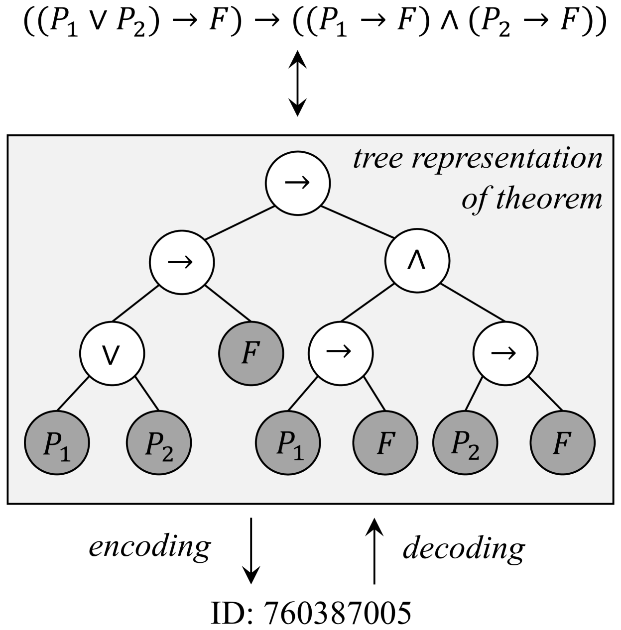
The image depicts a tree structure representing a logical theorem. The tree illustrates the decomposition of the logical expression `((P₁ ∨ P₂) → F)` into its constituent components, showing equivalence to `((P₁ → F) ∧ (P₂ → F))`. Arrows indicate hierarchical relationships, and nodes are labeled with logical operators (∨, →, ∧) and propositions (P₁, P₂, F). An encoding/decoding process is referenced via ID: 760387005.
### Components/Axes
- **Root Node**: `(P₁ ∨ P₂) → F`
- **Left Subtree**:
- Node: `(P₁ → F) ∧ (P₂ → F)`
- Branches:
- `(P₁ → F)` → Leaves: `P₁`, `F`
- `(P₂ → F)` → Leaves: `P₂`, `F`
- **Right Subtree**:
- Node: `(P₁ → F) ∧ (P₂ → F)` (identical to left subtree)
- Branches:
- `(P₁ → F)` → Leaves: `P₁`, `F`
- `(P₂ → F)` → Leaves: `P₂`, `F`
- **Encoding/Decoding Arrows**:
- Downward arrow labeled "encoding" points to ID: 760387005.
- Upward arrow labeled "decoding" points from ID: 760387005.
### Detailed Analysis
- **Logical Structure**:
- The root theorem `(P₁ ∨ P₂) → F` splits into two equivalent subtrees, each representing the conjunction `(P₁ → F) ∧ (P₂ → F)`.
- Each subtree further decomposes into implications:
- `P₁ → F` (if P₁ is true, then F must be true).
- `P₂ → F` (if P₂ is true, then F must be true).
- Leaves (`P₁`, `P₂`, `F`) represent atomic propositions.
- **Encoding/Decoding**:
- The ID `760387005` likely serves as a unique identifier for this theorem’s encoded representation.
- The bidirectional arrows suggest a reversible process between the theorem’s logical form and its encoded ID.
### Key Observations
1. **Symmetry**: Both subtrees under the root are identical, emphasizing the equivalence of `(P₁ ∨ P₂) → F` and `(P₁ → F) ∧ (P₂ → F)`.
2. **Atomic Propositions**: `P₁`, `P₂`, and `F` are terminal nodes, indicating they are foundational assumptions or variables.
3. **Encoding ID**: The ID `760387005` is centrally positioned, linking the logical structure to a computational or formal representation.
### Interpretation
This diagram demonstrates a fundamental logical equivalence in propositional logic:
- **Theorem**: `(P₁ ∨ P₂) → F` is logically equivalent to `(P₁ → F) ∧ (P₂ → F)`.
- This means "If either P₁ or P₂ is true, then F must be true" is equivalent to "P₁ implies F **and** P₂ implies F."
- **Encoding/Decoding**: The ID `760387005` suggests this theorem is part of a formal system (e.g., automated theorem proving, knowledge representation). The encoding process translates the logical structure into a machine-readable format, while decoding reverses this.
- **Significance**: The tree visually reinforces the decomposition of complex logical statements into simpler, verifiable components, aiding in proof construction or algorithmic verification.
No numerical data or trends are present; the focus is on logical relationships and structural representation.