## Conceptual Diagram: Biological Body Representations vs. Robot Performance
### Overview
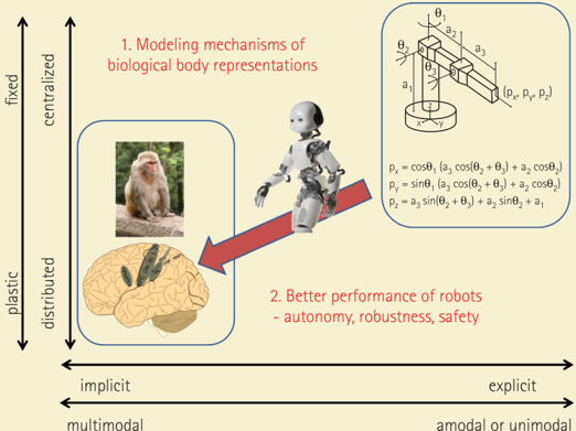
The image is a conceptual diagram illustrating the relationship between modeling mechanisms of biological body representations and achieving better performance in robots. It uses a 3D space defined by three axes: fixed/plastic, centralized/distributed, and implicit/explicit (multimodal/amodal or unimodal). The diagram suggests a progression from biological systems (monkey brain) to robotic systems, with an arrow indicating the direction of influence.
### Components/Axes
* **Axes:**
* Vertical Axis: "fixed" (top) to "plastic" (bottom)
* Vertical Axis (parallel): "centralized" (top) to "distributed" (bottom)
* Horizontal Axis: "implicit" (left) to "explicit" (right)
* Horizontal Axis (parallel): "multimodal" (left) to "amodal or unimodal" (right)
* **Elements:**
* Top-Left: Image of a monkey and the text "1. Modeling mechanisms of biological body representations" enclosed in a rounded rectangle.
* Bottom-Left: Image of a brain with highlighted regions.
* Center: Image of a humanoid robot.
* Top-Right: Diagram of a robotic arm with labeled components (a1, a2, a3, θ1, θ2, θ3, px, py, pz) and corresponding equations.
* pₓ = cosθ₁ (a₃ cos(θ₂ + θ₃) + a₂ cosθ₂)
* pᵧ = sinθ₁ (a₃ cos(θ₂ + θ₃) + a₂ cosθ₂)
* p₂ = a₃ sin(θ₂ + θ₃) + a₂ sinθ₂ + a₁
* Bottom-Center: Text "2. Better performance of robots - autonomy, robustness, safety" enclosed in a rounded rectangle.
* Red Arrow: Points from the monkey/robot area towards the brain area.
### Detailed Analysis
* **Fixed/Plastic Axis:** This axis likely refers to the rigidity or adaptability of the system. "Fixed" implies a pre-defined structure, while "plastic" suggests a system capable of learning and adapting.
* **Centralized/Distributed Axis:** This axis describes the location of control or processing. "Centralized" indicates a single control center, while "distributed" implies multiple, interconnected processing units.
* **Implicit/Explicit Axis:** This axis refers to the level of awareness or accessibility of the information. "Implicit" suggests subconscious or embedded knowledge, while "explicit" indicates readily available and understandable information.
* **Monkey/Robot Area:** The monkey and robot, along with the robotic arm diagram, are positioned towards the "fixed," "centralized," "explicit," and "amodal or unimodal" end of the spectrum.
* **Brain Area:** The brain image is positioned towards the "plastic," "distributed," "implicit," and "multimodal" end of the spectrum.
* **Arrow:** The red arrow indicates a flow or influence from the "fixed," "centralized," "explicit," and "amodal or unimodal" side (monkey/robot) to the "plastic," "distributed," "implicit," and "multimodal" side (brain).
### Key Observations
* The diagram contrasts biological systems (monkey brain) with robotic systems.
* The arrow suggests that insights from biological systems can inform the development of better robots.
* The axes highlight key differences between biological and robotic systems in terms of adaptability, control, and information representation.
### Interpretation
The diagram illustrates the idea that understanding how biological systems represent and control movement (e.g., the monkey's brain) can lead to improvements in robot design and performance. The progression from "fixed" and "centralized" robotic systems towards more "plastic" and "distributed" systems, inspired by biological models, could result in robots with greater autonomy, robustness, and safety. The diagram suggests that robots can benefit from incorporating principles of plasticity, distributed control, and multimodal sensory integration, which are characteristic of biological systems. The equations provided for the robotic arm likely represent a simplified kinematic model, which could be enhanced by incorporating more biologically-inspired control strategies.