# Technical Document Extraction: State Transition Diagram
## 1. Overview
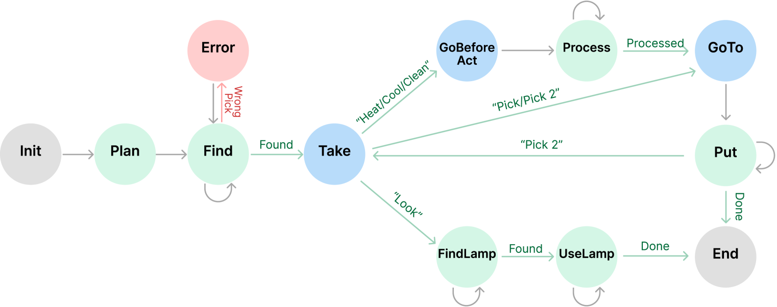
This image is a state transition diagram (finite state machine) illustrating a logical workflow for a robotic or automated task. The diagram uses circular nodes to represent states and directed arrows to represent transitions triggered by specific conditions or actions.
## 2. Component Isolation
The diagram is organized linearly from left to right, branching in the center into three primary functional paths before converging toward a final state.
### State Color Coding
* **Grey Nodes:** Initialization and Termination states (**Init**, **End**).
* **Light Green Nodes:** Operational/Action states (**Plan**, **Find**, **Process**, **Put**, **FindLamp**, **UseLamp**).
* **Light Blue Nodes:** Decision or Movement-oriented states (**Take**, **GoBeforeAct**, **GoTo**).
* **Light Red Node:** Error handling state (**Error**).
---
## 3. Detailed State and Transition Logic
### Phase 1: Initialization and Discovery
| Source State | Transition Label | Target State | Description |
| :--- | :--- | :--- | :--- |
| **Init** | (unlabeled) | **Plan** | System starts and moves to planning. |
| **Plan** | (unlabeled) | **Find** | Planning leads to the search phase. |
| **Find** | (self-loop) | **Find** | Continuous searching until the object is located. |
| **Find** | "Wrong Pick" (Red) | **Error** | Transition to error state if an incorrect item is selected. |
| **Error** | (unlabeled) | **Find** | Recovery path from error back to searching. |
| **Find** | "Found" (Green) | **Take** | Successful identification leads to the Take state. |
### Phase 2: Branching Logic (From "Take")
From the **Take** state, the workflow branches based on the required action:
1. **Path A: Processing Path**
* **Take** $\xrightarrow{\text{"Heat/Cool/Clean"}}$ **GoBeforeAct**
* **GoBeforeAct** $\xrightarrow{\text{(unlabeled)}}$ **Process**
* **Process** $\xrightarrow{\text{(self-loop)}}$ **Process** (Indicates ongoing processing)
* **Process** $\xrightarrow{\text{"Processed"}}$ **GoTo**
2. **Path B: Direct Movement Path**
* **Take** $\xrightarrow{\text{"Pick/Pick 2"}}$ **GoTo**
3. **Path C: Visual/Auxiliary Path**
* **Take** $\xrightarrow{\text{"Look"}}$ **FindLamp**
* **FindLamp** $\xrightarrow{\text{(self-loop)}}$ **FindLamp**
* **FindLamp** $\xrightarrow{\text{"Found"}}$ **UseLamp**
* **UseLamp** $\xrightarrow{\text{(self-loop)}}$ **UseLamp**
* **UseLamp** $\xrightarrow{\text{"Done"}}$ **End**
### Phase 3: Placement and Completion
| Source State | Transition Label | Target State | Description |
| :--- | :--- | :--- | :--- |
| **GoTo** | (unlabeled) | **Put** | Movement to the destination for placement. |
| **Put** | (self-loop) | **Put** | Action of placing the object. |
| **Put** | "Pick 2" | **Take** | A feedback loop allowing for a second pick action after a placement. |
| **Put** | "Done" | **End** | Final completion of the task. |
---
## 4. Summary of Textual Labels
* **States:** Init, Plan, Find, Error, Take, GoBeforeAct, Process, GoTo, Put, FindLamp, UseLamp, End.
* **Transition Conditions:**
* **Success/Status:** Found, Processed, Done.
* **Actions/Commands:** "Heat/Cool/Clean", "Pick/Pick 2", "Look", "Pick 2".
* **Failure:** Wrong Pick.
## 5. Spatial Grounding and Flow Analysis
* **Horizontal Flow:** The primary logic flows from **Init** (far left) to **End** (far right).
* **Vertical Hierarchy:** The **Error** state is positioned above the main line, indicating an exception. The branching paths from **Take** occupy the upper, middle, and lower-right quadrants of the diagram.
* **Feedback Loops:** There are five self-looping arrows (**Find**, **Process**, **Put**, **FindLamp**, **UseLamp**) indicating iterative processes, and one major feedback loop from **Put** back to **Take**.