# Technical Document Extraction: Flowchart Analysis
## Diagram Overview
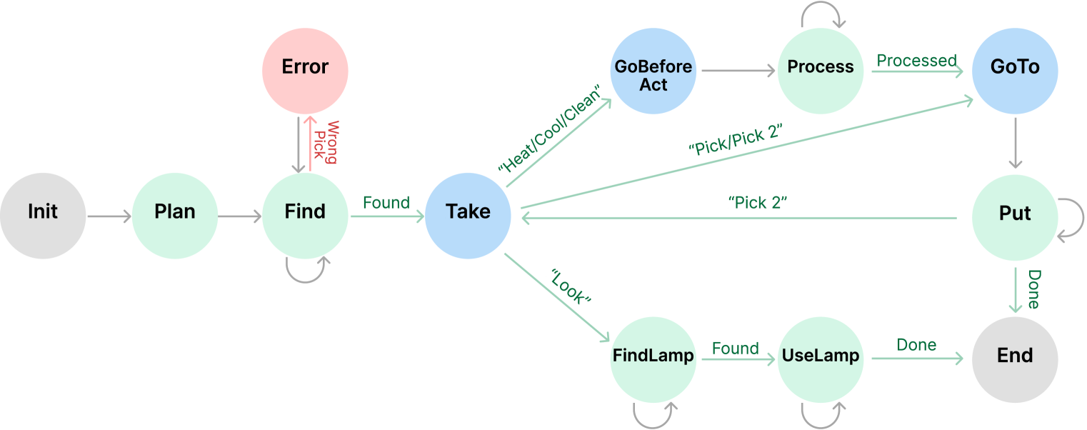
The image depicts a state machine or workflow diagram with **12 nodes** and **15 transitions**. Nodes are color-coded (gray, green, blue, red) and labeled with actions/states. Transitions include conditional logic and action descriptors.
---
## Node Definitions
### Gray Nodes (Start/End States)
1. **Init**
- Start of workflow
- Transition: `→ Plan` (no label)
2. **End**
- Final state
- Incoming transitions:
- `→ Done` (from `Put`)
- `→ Done` (from `UseLamp`)
### Green Nodes (Process States)
3. **Plan**
- Transition: `← Init` (no label)
- Transition: `→ Find` (no label)
4. **Find**
- Self-loop: `↔` (no label)
- Transition: `→ Take` (labeled `Found`)
- Error path: `→ Error` (labeled `Wrong Pick`)
5. **Process**
- Incoming: `→ Process` (from `GoBeforeAct`)
- Outgoing: `→ GoTo` (labeled `Processed`)
6. **FindLamp**
- Self-loop: `↔` (no label)
- Transition: `→ UseLamp` (labeled `Found`)
7. **UseLamp**
- Self-loop: `↔` (no label)
- Transition: `→ End` (labeled `Done`)
### Blue Nodes (Action States)
8. **Take**
- Central decision node
- Outgoing transitions:
- `→ FindLamp` (labeled `“Look”`)
- `→ Process` (labeled `“Heat/Cool/Clean”`)
- `→ Put` (labeled `“Pick/Pick 2”`)
9. **GoBeforeAct**
- Incoming: `← Take` (labeled `“Heat/Cool/Clean”`)
- Outgoing: `→ Process` (no label)
10. **GoTo**
- Incoming: `→ GoTo` (from `Process`)
- Outgoing: `→ Put` (labeled `“Pick 2”`)
11. **Put**
- Incoming:
- `→ Put` (from `GoTo`)
- `→ Put` (from `Take`)
- Outgoing: `→ End` (labeled `Done`)
### Red Node (Error State)
12. **Error**
- Incoming: `→ Error` (from `Find`)
- No outgoing transitions
---
## Key Trends and Logic Flow
1. **Primary Workflow**
`Init → Plan → Find → Take → [FindLamp → UseLamp → End]`
- `Find` loops until `Found` condition met
- `UseLamp` loops until `Done` condition met
2. **Alternative Paths**
- **Heat/Cool/Clean Path**:
`Take → GoBeforeAct → Process → GoTo → Put → End`
- **Pick/Pick 2 Path**:
`Take → Put → End`
3. **Error Handling**
- `Find` node triggers `Error` on `Wrong Pick` condition
---
## Spatial Grounding and Color Mapping
- **Legend**:
- Gray: `Init`, `End`
- Green: `Plan`, `Find`, `Process`, `Put`, `FindLamp`, `UseLamp`
- Blue: `Take`, `GoBeforeAct`, `GoTo`
- Red: `Error`
- **Transition Labels**:
- `Found`, `Processed`, `Done` (success states)
- `“Look”`, `“Heat/Cool/Clean”`, `“Pick/Pick 2”` (action conditions)
- `Wrong Pick` (error condition)
---
## Component Isolation
### Header
- No explicit header; workflow begins at `Init`.
### Main Chart
- Central node: `Take` (blue) with three decision branches.
- Critical loops:
- `Find` ↔ `Find` (green)
- `UseLamp` ↔ `UseLamp` (green)
### Footer
- `End` node aggregates all successful paths.
---
## Data Extraction Summary
| Node | Type | Connections |
|---------------|------------|-----------------------------------------------------------------------------|
| Init | Start | → Plan |
| Plan | Process | ← Init, → Find |
| Find | Process | ← Take, → Take (Found), → Error (Wrong Pick), ↔ Find |
| Take | Action | ← Find (Found), → FindLamp (“Look”), → Process (“Heat/Cool/Clean”), → Put (“Pick/Pick 2”) |
| GoBeforeAct | Action | ← Take (“Heat/Cool/Clean”), → Process |
| Process | Process | ← GoBeforeAct, → GoTo (Processed) |
| GoTo | Action | ← Process, → Put (“Pick 2”) |
| Put | Process | ← GoTo, → Take (“Pick 2”), → End (Done) |
| FindLamp | Process | ← Take (“Look”), → UseLamp (Found), ↔ FindLamp |
| UseLamp | Process | ← FindLamp (Found), → End (Done), ↔ UseLamp |
| End | End | ← Put (Done), ← UseLamp (Done) |
| Error | Error | ← Find (Wrong Pick) |
---
## Notes
- No numerical data or charts present; purely logical flow diagram.
- All transitions are labeled with conditions or actions.
- Self-loops indicate retry logic for `Find` and `UseLamp`.
- Error state is terminal with no recovery path.