\n
## Network Diagram: Bidirectional Communication Structure
### Overview
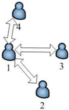
The image displays a simple network diagram consisting of four human-shaped silhouette icons (nodes) connected by double-headed arrows, indicating bidirectional relationships or communication channels. The diagram is presented on a plain white background with no additional text, titles, or legends.
### Components/Axes
* **Nodes:** Four identical blue human silhouette icons.
* **Labels:** Each node is labeled with a black numeral placed to its immediate right.
* Node labeled **1** is positioned in the center-left area.
* Node labeled **2** is positioned at the bottom-center.
* Node labeled **3** is positioned on the right side.
* Node labeled **4** is positioned at the top-center.
* **Connections (Edges):** Three double-headed, gray arrows indicating mutual, two-way connections.
* An arrow connects Node **1** and Node **4**.
* An arrow connects Node **1** and Node **3**.
* An arrow connects Node **1** and Node **2**.
### Detailed Analysis
The diagram illustrates a specific network topology. The connections are not uniform; they form a star or hub-and-spoke pattern centered on Node 1.
* **Node 1 (Central Hub):** This node has direct, bidirectional connections to all three other nodes (2, 3, and 4). It acts as the central point of the network.
* **Node 2 (Peripheral):** Has a single bidirectional connection, exclusively with Node 1.
* **Node 3 (Peripheral):** Has a single bidirectional connection, exclusively with Node 1.
* **Node 4 (Peripheral):** Has a single bidirectional connection, exclusively with Node 1.
There are **no direct connections** between the peripheral nodes (2, 3, and 4). All communication or interaction between them must be routed through the central hub, Node 1.
### Key Observations
1. **Asymmetric Connectivity:** The network is highly centralized. Node 1 has a degree of 3 (three connections), while Nodes 2, 3, and 4 each have a degree of 1.
2. **Bidirectional Flow:** All arrows are double-headed, signifying that relationships or data flows are mutual and two-way between connected pairs.
3. **Spatial Layout:** The positioning of nodes appears deliberate for clarity. Node 1 is centrally located relative to the others, visually reinforcing its role as the hub. The peripheral nodes are spaced around it (top, right, bottom).
### Interpretation
This diagram models a centralized communication or organizational structure. It suggests a system where a single entity (Node 1) is the essential conduit for all interactions between the other members (Nodes 2, 3, 4).
* **Function:** This could represent a team where one person is the primary coordinator, a computer network with a central server, or a social group with a key connector.
* **Implications:** The structure highlights both efficiency and vulnerability. It is efficient for controlled information flow from the center but creates a single point of failure. If Node 1 is removed, the network fragments into three isolated nodes. The peripheral nodes are dependent on the hub for any connection to the wider network.
* **Underlying Message:** The visual emphasizes hierarchy and dependency more than egalitarian collaboration. The lack of cross-connections between 2, 3, and 4 implies siloed relationships mediated entirely by the central figure.