## Diagram: Finite State Automaton
### Overview
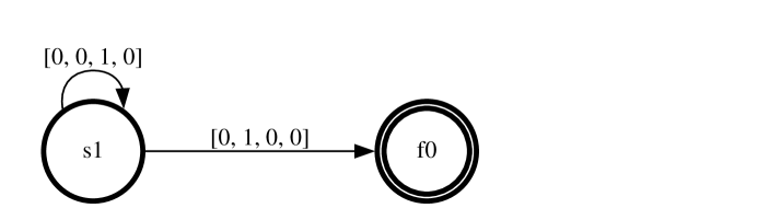
The image depicts a finite state automaton (FSA) with two states, 's1' and 'f0'. The automaton transitions from state 's1' to state 'f0' upon receiving the input '[0, 1, 0, 0]'. State 's1' also has a self-loop transition upon receiving the input '[0, 0, 1, 0]'. State 'f0' is a final (accepting) state, indicated by the double circle. The right side of the image is shaded gray.
### Components/Axes
* **States:**
* 's1': Initial state, represented by a single circle. Located on the left side of the diagram.
* 'f0': Final state, represented by a double circle. Located on the right side of the diagram, in the gray shaded area.
* **Transitions:**
* From 's1' to 'f0': Labeled with '[0, 1, 0, 0]'.
* Self-loop on 's1': Labeled with '[0, 0, 1, 0]'.
* **Input Symbols:** The input symbols are represented as vectors of four binary digits.
### Detailed Analysis or ### Content Details
* **State 's1':**
* A transition labeled '[0, 0, 1, 0]' loops back to 's1'. The arrow indicates the direction of the transition.
* A transition labeled '[0, 1, 0, 0]' leads to state 'f0'. The arrow indicates the direction of the transition.
* **State 'f0':**
* 'f0' is a final state, indicated by the double circle. There are no outgoing transitions from 'f0' shown in the diagram.
### Key Observations
* The automaton starts in state 's1'.
* The automaton accepts the input sequence '[0, 1, 0, 0]' by transitioning to the final state 'f0'.
* The automaton can remain in state 's1' indefinitely by repeatedly receiving the input '[0, 0, 1, 0]'.
### Interpretation
The diagram represents a simple finite state automaton that recognizes a specific input sequence. The automaton transitions from an initial state to a final state upon receiving the input '[0, 1, 0, 0]'. The self-loop on state 's1' allows the automaton to remain in that state while receiving the input '[0, 0, 1, 0]'. The gray shading on the right side of the image does not appear to have any functional significance within the FSA itself.