## Diagram: L1 TCDM and IMA Architecture
### Overview
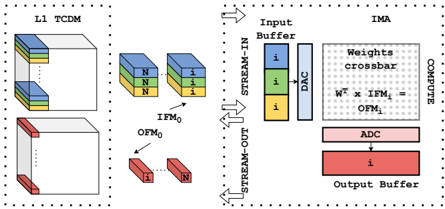
The image presents a block diagram illustrating the architecture of L1 TCDM (likely a memory component) and IMA (likely an image processing accelerator). It depicts data flow between these components, highlighting input and output buffers, weight crossbar, and analog-to-digital conversion (ADC) processes.
### Components/Axes
* **L1 TCDM (Left Side)**:
* Two 3D cube-like structures, representing memory blocks.
* The top cube has blue and yellow sections in the top-left corner.
* The bottom cube has red sections in the bottom-left corner.
* Diagrams showing data transformation from IFM0 to OFM0.
* IFM0 consists of three stacked blocks colored blue, green, and yellow, labeled with "N" and "i".
* OFM0 consists of two blocks colored red, labeled with "i" and "N".
* **IMA (Right Side)**:
* Input Buffer: Contains three blocks colored blue, green, and yellow, each labeled "i".
* DAC (Digital-to-Analog Converter): Converts digital input to analog.
* Weights crossbar: Represents the weight matrix used in computation.
* Computation Block: Shows the matrix multiplication W^T x IFMi = OFMi.
* ADC (Analog-to-Digital Converter): Converts analog output to digital.
* Output Buffer: Contains a red block labeled "i".
* **Data Flow**:
* STREAM-IN: Data flows into the IMA from the top-left.
* STREAM-OUT: Data flows out of the IMA from the bottom-left.
* COMPUTE: Indicates the computation stage within the IMA.
### Detailed Analysis
* **L1 TCDM**:
* The top cube has a blue section that occupies approximately 1/8 of the cube's volume, and a yellow section that occupies approximately 1/8 of the cube's volume.
* The bottom cube has a red section that occupies approximately 1/8 of the cube's volume.
* The IFM0 data transformation shows three blocks stacked vertically, colored blue, green, and yellow. The blocks are labeled "N" and "i".
* The OFM0 data transformation shows two blocks, colored red, labeled "i" and "N".
* **IMA**:
* The Input Buffer contains three blocks, colored blue, green, and yellow, each labeled "i".
* The DAC is a single block.
* The Weights crossbar is represented as a grid.
* The computation block shows the equation W^T x IFMi = OFMi.
* The ADC is a single block.
* The Output Buffer contains a red block labeled "i".
* **Data Flow**:
* STREAM-IN: Data flows into the Input Buffer.
* STREAM-OUT: Data flows out of the Output Buffer.
* COMPUTE: The computation involves the Weights crossbar and the ADC.
### Key Observations
* The diagram illustrates the flow of data from L1 TCDM to IMA.
* The data transformation from IFM0 to OFM0 is shown.
* The computation within the IMA involves a weight crossbar and ADC.
* The colors blue, green, yellow, and red are used to represent different data types or stages.
### Interpretation
The diagram provides a high-level overview of the architecture and data flow between L1 TCDM and IMA. The L1 TCDM likely serves as a memory component, providing input data (IFM0) to the IMA. The IMA performs computations using a weight crossbar and ADC, producing output data (OFM0). The STREAM-IN and STREAM-OUT arrows indicate the direction of data flow. The colors may represent different data types or stages in the processing pipeline. The diagram suggests a hardware architecture optimized for image processing or similar tasks involving matrix multiplication.