## Diagram: Neural Network Processing Pipeline with In-Memory Architecture (IMA)
### Overview
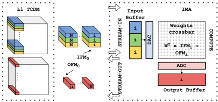
The diagram illustrates a two-stage neural network processing pipeline. On the left, a Layer 1 Temporal Convolutional Memory (TCDM) processes input data through two distinct pathways (top and bottom blocks). On the right, an In-Memory Architecture (IMA) handles data flow through a crossbar array, analog-to-digital conversion (ADC), and output buffering. The system emphasizes stream-in/stream-out data movement and computational efficiency.
---
### Components/Axes
#### Left Diagram (L1 TCDM)
- **Blocks**:
- Top block: Three layers labeled `N` (blue), `N` (green), `i` (yellow).
- Bottom block: Two layers labeled `i` (red), `N` (yellow).
- **Outputs**:
- `IFM₀` (Input Feature Map 0) from top block.
- `OFM₀` (Output Feature Map 0) from bottom block.
- **Legend**:
- Blue = `i` (input), Green = `N` (neuron/feature map), Yellow = `i`, Red = `i`.
#### Right Diagram (IMA)
- **Components**:
1. **Input Buffer**: Three layers labeled `i` (blue, green, yellow).
2. **DAC** (Digital-to-Analog Converter): Converts digital signals to analog.
3. **Weights Crossbar**: Matrix operation `Wᵀ × IFM₁ = OFM₁` (transposed weights multiplied by input feature map).
4. **ADC** (Analog-to-Digital Converter): Converts analog signals back to digital.
5. **Output Buffer**: Single layer labeled `i` (red).
- **Legend**:
- Blue = `i` (input), Green = `N` (neuron/feature map), Yellow = `i`, Pink = ADC, Red = Output Buffer.
---
### Detailed Analysis
#### Left Diagram (L1 TCDM)
- **Top Block**:
- Three sequential layers: Two `N` (neuron/feature map) layers followed by an `i` (input) layer.
- Outputs `IFM₀`, suggesting intermediate feature map generation.
- **Bottom Block**:
- Two layers: `i` (input) followed by `N` (neuron/feature map).
- Outputs `OFM₀`, indicating final feature map output.
- **Flow**: Data flows from top to bottom blocks via dotted lines, implying parallel processing.
#### Right Diagram (IMA)
- **Input Buffer**:
- Three `i` (input) layers, possibly representing raw data samples.
- **DAC**: Converts digital input to analog for crossbar processing.
- **Weights Crossbar**:
- Performs matrix multiplication (`Wᵀ × IFM₁`) to compute `OFM₁` (output feature map).
- Colors in crossbar align with legend: Blue (`i`), Green (`N`), Yellow (`i`).
- **ADC**: Converts analog output from crossbar to digital.
- **Output Buffer**: Stores final `i` (input) data in red.
---
### Key Observations
1. **Color-Label Mismatch**:
- The Input Buffer’s green layer is labeled `i` (input), conflicting with the legend’s green = `N` (neuron/feature map). This may indicate a labeling error or contextual reuse of `i`.
2. **Crossbar Computation**:
- The equation `Wᵀ × IFM₁ = OFM₁` suggests a linear algebra operation central to the IMA’s function.
3. **Stream-In/Stream-Out**:
- Arrows indicate bidirectional data flow, emphasizing real-time processing.
4. **Component Isolation**:
- Left diagram focuses on feature map generation; right diagram emphasizes analog/digital conversion and matrix operations.
---
### Interpretation
This diagram represents a hybrid neural network architecture combining temporal convolutional processing (L1 TCDM) with analog in-memory computing (IMA). The left side likely models sequential feature extraction, while the right side optimizes computation via crossbar arrays and analog-digital conversion. The color-coding (blue/green/yellow/red) differentiates data types (`i`, `N`, ADC, Output Buffer), though inconsistencies in labeling (e.g., green `i` vs. `N`) suggest potential ambiguities in the system’s design. The use of `Wᵀ × IFM₁` highlights the IMA’s role in efficient matrix multiplication, critical for deep learning workloads. The bidirectional flow arrows imply a focus on low-latency, real-time data processing.