## Diagram: Bidirectional System Interaction with Feedback Loops
### Overview
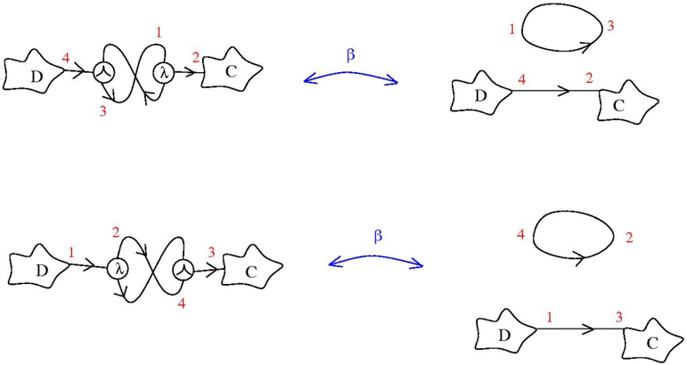
The image depicts two interconnected diagrams representing systems or processes labeled **D** (left) and **C** (right), linked by a bidirectional arrow labeled **β**. Each diagram contains nested loops with numbered components (1–4) and directional arrows labeled **λ**. The diagrams suggest a relationship between **D** and **C** mediated by feedback mechanisms.
---
### Components/Axes
- **Nodes/Entities**:
- **D**: Left-side system/component.
- **C**: Right-side system/component.
- **Arrows**:
- **λ**: Unidirectional arrows within each diagram (top and bottom loops).
- **β**: Bidirectional arrow connecting **D** and **C** between diagrams.
- **Labels**:
- Numbers **1–4** annotate loops in both diagrams.
- Greek letter **λ** marks internal directional flows.
---
### Detailed Analysis
#### Top Diagram:
1. **Loop Structure**:
- **D → λ → Loop 1 → λ → Loop 2 → λ → C**.
- Numbers **1, 2, 3, 4** label transitions within the loop.
2. **Flow**:
- Input from **D** enters a nested loop (1→2→3→4) before exiting to **C**.
#### Bottom Diagram:
1. **Loop Structure**:
- **D → λ → Loop 1 → λ → Loop 2 → λ → C**.
- Numbers **1, 2, 3, 4** label transitions, but the loop order differs (e.g., 4→2 in the final loop).
2. **Flow**:
- Input from **D** traverses a modified loop (1→2→3→4) before exiting to **C**.
#### Bidirectional Connection (β):
- **β** links the two diagrams, implying mutual influence or exchange between **D** and **C**.
---
### Key Observations
1. **Loop Variations**:
- The top and bottom diagrams share similar loop structures but differ in numerical labeling (e.g., **4→2** in the bottom diagram vs. **3→4** in the top).
2. **Bidirectional β**:
- The **β** arrow suggests **D** and **C** interact reciprocally, possibly indicating feedback or synchronization.
3. **λ Arrows**:
- Unidirectional **λ** arrows within loops imply sequential processing or transformation steps.
---
### Interpretation
- **System Dynamics**:
The diagrams likely model a process where **D** and **C** are interdependent systems. The nested loops (1–4) represent stages of transformation or feedback within each system, while **β** enables cross-system interaction.
- **Functional Relationships**:
- **λ** arrows denote directional causality (e.g., **D** influences **C** via intermediate steps).
- **β** suggests **C** can also influence **D**, creating a closed-loop system.
- **Anomalies**:
The differing numerical labels in the loops (e.g., **4→2** vs. **3→4**) may indicate alternative pathways or conditional logic within the systems.
---
### Conclusion
This diagram illustrates a bidirectional relationship between **D** and **C**, mediated by nested feedback loops. The use of **λ** and **β** highlights directional and reciprocal interactions, respectively. The numerical labels (1–4) likely encode process steps or component dependencies, with variations between diagrams suggesting adaptability or alternative states in the system.