## Diagram: Neural Network Architecture for Entity-Relation Association
### Overview
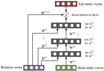
The image displays a schematic diagram of a neural network architecture, likely designed for knowledge graph embedding or relational learning. It illustrates how a "Head entity vector" and a "Relation vector" are processed through multiple layers to predict or associate with a "Tail entity vector." The flow is bottom-up, with information from the head and relation vectors being combined and transformed through a series of layers before reaching a final association function.
### Components/Axes
The diagram is composed of several key components, arranged vertically:
1. **Input Vectors (Bottom):**
* **Head entity vector:** A green rectangular box containing four circles, representing a vector. Located at the bottom-right.
* **Relation vector:** A purple rectangular box containing four circles, representing a vector. Located at the bottom-left.
2. **Processing Layers (Middle):**
* A stack of four gray rectangular boxes, each containing four circles, representing hidden layers or transformation blocks. They are arranged vertically in the center.
* Each layer is labeled with input (`In:`) and output (`out:`) notations and connected by arrows indicating data flow.
* **Layer 1 (Bottom-most gray box):** Labeled `out: z^(1)` and `In: a^(1)`. An arrow labeled `W^(1)` points from the Head entity vector into this layer.
* **Layer 2:** Labeled `out: z^(2)` and `In: a^(2)`. An arrow labeled `W^(2)` points from Layer 1 into this layer.
* **Ellipsis (Vertical dots):** Indicates additional, unspecified layers between Layer 2 and Layer L.
* **Layer L (Top-most gray box):** Labeled `out: z^(L)` and `In: a^(L)`. An arrow labeled `W^(L)` points from the layer below (implied Layer L-1) into this layer.
3. **Association Function (Top-Middle):**
* A circular node labeled `f`.
* An arrow labeled `B^(L+1)` points from the top of the Layer L box into this function node.
* Text to the right of the node reads: "Association at here".
4. **Output Vector (Top):**
* **Tail entity vector:** A red rectangular box containing four circles, representing the target vector. Located at the top-center.
* An arrow points from the function node `f` into this Tail entity vector box.
5. **Skip Connections / Direct Paths:**
* Arrows labeled `B^(1)`, `B^(2)`, ..., `B^(L)` originate from the **Relation vector** box.
* These arrows bypass the main layer stack and connect directly to the input side of their corresponding layers:
* `B^(1)` connects to the input of Layer 1.
* `B^(2)` connects to the input of Layer 2.
* `B^(L)` connects to the input of Layer L.
* This suggests the relation information is injected directly into each processing layer.
### Detailed Analysis
* **Flow Direction:** The primary data flow is upward (bottom-to-top). The Head entity vector is transformed by weight matrix `W^(1)` to produce the input `a^(1)` for the first layer. The output `z^(1)` of the first layer becomes part of the input for the second layer via `W^(2)`, and so on.
* **Relation Integration:** The Relation vector is not processed sequentially. Instead, it provides direct, parallel input (`B^(1)`, `B^(2)`, ..., `B^(L)`) to every layer in the stack, indicating its fundamental role in modulating the transformation at each stage.
* **Final Association:** The final processed representation from Layer L (`z^(L)`) is passed through a function `f` (likely a similarity or scoring function) along with the direct transformation `B^(L+1)` of the relation vector. The output of `f` is associated with the Tail entity vector, suggesting the model's goal is to compute a score or probability for the (head, relation, tail) triplet.
* **Mathematical Notation:** The superscripts `(1), (2), ..., (L), (L+1)` denote the layer or stage index. `W` and `B` represent learnable weight matrices or transformation parameters. `a` and `z` likely represent activation and output vectors for a layer, respectively.
### Key Observations
1. **Hybrid Architecture:** The model combines a sequential, deep processing path (for the head entity) with a parallel, direct integration path (for the relation). This is a distinctive architectural choice.
2. **Layer-wise Relation Conditioning:** The relation vector influences every layer of the head entity's transformation, not just the input or output. This suggests the relation is a continuous, guiding context throughout the computation.
3. **Function `f` as the Decision Point:** The final association is not a simple vector comparison but involves a dedicated function `f` that takes inputs from both the deep processing stream and a direct relation transformation (`B^(L+1)`).
### Interpretation
This diagram represents a **deep relational network** for knowledge graph completion or reasoning. The core idea is to learn how a given relation (`R`) transforms a head entity (`H`) into a tail entity (`T`). The architecture suggests a sophisticated approach where:
* The **head entity** undergoes a deep, non-linear transformation (`W` layers) to build a rich representation.
* The **relation** acts as a dynamic filter or modulator, directly conditioning each step of the head entity's transformation via the `B` connections. This is more powerful than simply adding or concatenating the relation at the start.
* The final **association function `f`** (e.g., a dot product, a small neural network) compares the deeply processed head-relation representation with the candidate **tail entity vector** to produce a score.
The model's design implies that understanding the interaction between entities requires both deep feature extraction (the layered `W` path) and precise, context-aware modulation (the parallel `B` path). The "Association at here" label highlights that the critical inference happens at the function `f`, which synthesizes all processed information to make a prediction. This architecture would be used to predict missing links in a knowledge graph (e.g., given "Paris" and "isCapitalOf", predict "France") or to score the validity of known facts.