\n
## Diagram: Graph Structures with Node Types
### Overview
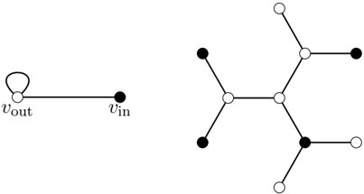
The image displays two distinct graph diagrams composed of nodes (vertices) and edges (connections). The left diagram is a simple two-node graph with a self-loop, while the right diagram is a more complex, tree-like network. The nodes are differentiated by fill color: some are solid black, others are empty white circles. There is no explicit legend, but the color appears to denote a categorical property of the nodes.
### Components/Axes
* **Left Diagram:**
* **Nodes:** Two nodes.
* Left node: An empty white circle labeled **`v_out`**.
* Right node: A solid black circle labeled **`v_in`**.
* **Edges:** One straight line connecting `v_out` and `v_in`. One curved line forming a **self-loop** on the `v_out` node.
* **Right Diagram:**
* **Nodes:** A total of 11 nodes.
* **Solid Black Nodes:** 5 nodes.
* **Empty White Nodes:** 6 nodes.
* **Edges:** 10 straight lines connecting the nodes in a branching, non-cyclic structure. The central node is an empty white circle.
* **Spatial Layout:** The two diagrams are placed side-by-side. The simpler graph is on the left, and the more complex graph is on the right. There is no title, axis, or numerical data present.
### Detailed Analysis
* **Left Graph Structure:** This represents a minimal directed graph or state machine. The edge from `v_in` to `v_out` suggests a flow or transition from an input state to an output state. The self-loop on `v_out` indicates that the output state can transition to itself, representing a stable state, a recursive operation, or a feedback loop.
* **Right Graph Structure:** This is an undirected tree or network graph. It has a central hub (an empty white node) from which three main branches emanate.
* **Branch 1 (Top):** Connects to an empty white node, which then connects to a terminal solid black node.
* **Branch 2 (Left):** Connects to an empty white node, which then connects to two terminal solid black nodes.
* **Branch 3 (Bottom-Right):** Connects to a solid black node, which then connects to two terminal empty white nodes.
* **Node Color Pattern:** There is no strict rule that all leaf nodes are one color. Terminal nodes can be either black or white. The central node and several intermediate nodes are white, while some intermediate and terminal nodes are black. This suggests the color may represent a property like "active/inactive," "type A/type B," or "input/output" that is not determined solely by the node's position in the hierarchy.
### Key Observations
1. **Asymmetry in Complexity:** The image juxtaposes a fundamental graph motif (left) with a more elaborate network built from similar elements (right).
2. **Color as the Sole Differentiator:** In the absence of textual labels on the right graph, the black/white fill is the only visual cue to distinguish node types or states.
3. **Mixed Connectivity:** The right graph shows that nodes of the same color (e.g., white) can be connected to each other, and nodes of different colors are also connected. There is no visible segregation by color.
4. **Structural Role vs. Color:** A node's structural importance (e.g., being a central hub) does not correlate with a specific color. The central hub is white, but other white nodes are peripheral.
### Interpretation
This diagram likely serves as an abstract representation in fields like **graph theory, computer science, or network analysis**. It visually communicates concepts about node classification and network topology.
* **The Left Graph** acts as a **legend or key**, defining the two fundamental node types (`v_in` as black, `v_out` as white) and a basic relational motif (input feeds output, which has self-feedback).
* **The Right Graph** demonstrates how these node types can be assembled into a larger, more complex structure. It shows that the relationship between node type (color) and network position is not fixed; both black and white nodes can serve as hubs, intermediaries, or terminals.
* **The Underlying Message:** The diagram emphasizes that **function or state (indicated by color) is independent of structural position**. A node's role in the network (central, bridging, terminal) is a separate property from its intrinsic type. This is a common concept in modeling systems like neural networks (where neurons have types), social networks (where individuals have attributes), or distributed systems (where nodes have different functions).
**Language Note:** The only text present is the mathematical notation `v_out` and `v_in`, which are standard subscripts in English-language technical documents. No other language is present.