\n
## Diagram: Data Embedding Scheme
### Overview
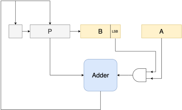
The image depicts a diagram illustrating a data embedding scheme, likely for steganography or watermarking. It shows how data 'A' is embedded into a carrier signal 'P' using an adder and a least significant bit (LSB) modification technique. The diagram outlines the flow of data and the components involved in the embedding process.
### Components/Axes
The diagram consists of the following components:
* **Input Signal:** Represented by a grey rectangle with an arrow entering from the top.
* **P:** A rectangular block labeled "P", representing the carrier signal.
* **A:** A rectangular block labeled "A", representing the data to be embedded.
* **B:** A rectangular block labeled "B" with the annotation "LSB", indicating the least significant bit.
* **Adder:** A rectangular block labeled "Adder", performing the addition operation.
* **XOR Gate:** A logic gate labeled with the XOR symbol.
* **Arrows:** Indicate the direction of data flow between components.
### Detailed Analysis or Content Details
The diagram illustrates the following data flow:
1. The input signal flows into block 'P'.
2. Block 'P' also receives a feedback loop from the output of the Adder.
3. Data 'A' is input into an XOR gate.
4. The LSB of 'B' is also input into the XOR gate.
5. The output of the XOR gate is fed into the Adder.
6. The Adder receives input from 'P' and the XOR gate.
7. The output of the Adder is fed back into 'P' via a feedback loop.
There are no numerical values or scales present in the diagram. It is a conceptual representation of a process.
### Key Observations
The diagram highlights the use of the LSB of 'B' for embedding data 'A'. The XOR gate likely serves to modulate the data 'A' before embedding it into the carrier signal 'P'. The feedback loop suggests that the embedding process might be iterative or adaptive.
### Interpretation
This diagram demonstrates a basic data embedding technique. The data 'A' is hidden within the carrier signal 'P' by modifying the least significant bit of 'B' and adding it to 'P' using an adder. The XOR gate likely ensures that the embedded data is not easily detectable without knowing the key (the LSB of 'B'). This technique is commonly used in steganography to conceal information within other data, such as images or audio files. The feedback loop suggests a potential mechanism for error correction or adaptive embedding, where the embedding process adjusts based on the characteristics of the carrier signal. The diagram is a simplified representation and does not include details about the specific implementation of the adder, XOR gate, or the carrier signal 'P'.