## Diagram: Mach-Zehnder Interferometer
### Overview
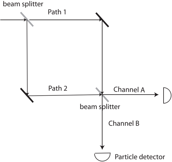
The image is a schematic diagram of a Mach-Zehnder interferometer. It illustrates the path of a particle or wave through the interferometer, which consists of two beam splitters and two mirrors arranged to create two distinct paths. The diagram shows how the particle/wave is split, recombined, and detected.
### Components/Axes
* **Beam Splitter (Top-Left):** A device that splits the incoming beam into two paths.
* **Beam Splitter (Center):** A device that recombines the beams from the two paths.
* **Mirror (Top-Right):** A reflective surface that redirects the beam along Path 1.
* **Mirror (Bottom-Left):** A reflective surface that redirects the beam along Path 2.
* **Path 1:** The upper path of the interferometer.
* **Path 2:** The lower path of the interferometer.
* **Channel A:** The output channel leading to a detector (labeled "D").
* **Channel B:** The output channel leading to a particle detector.
* **Particle Detector:** A detector at the end of Channel B.
* **D:** A detector at the end of Channel A.
### Detailed Analysis
The diagram shows a single input beam entering from the left.
1. **First Beam Splitter:** The initial beam splitter divides the beam into two paths: Path 1 (upper) and Path 2 (lower).
2. **Path 1:** The beam travels upward to a mirror, which reflects it to the right, towards the second beam splitter.
3. **Path 2:** The beam travels downward to a mirror, which reflects it to the right, towards the second beam splitter.
4. **Second Beam Splitter:** The beams from Path 1 and Path 2 recombine at the second beam splitter. This beam splitter directs the beams into two output channels: Channel A and Channel B.
5. **Channel A:** The beam travels to a detector labeled "D".
6. **Channel B:** The beam travels to a particle detector.
### Key Observations
* The diagram illustrates the fundamental components and layout of a Mach-Zehnder interferometer.
* The beam splitters are represented by a line with a diagonal gray line.
* The mirrors are represented by a line with a diagonal black line.
* The detectors are represented by a semi-circle.
### Interpretation
The Mach-Zehnder interferometer is a device used to demonstrate wave-particle duality and quantum interference. The diagram illustrates how a single particle or wave can be split into two paths and then recombined, leading to interference effects at the detectors. The relative path lengths of Path 1 and Path 2 determine the interference pattern observed at the detectors in Channel A and Channel B. The presence of detectors in both channels allows for the observation of which-path information, which can affect the interference pattern.