## Diagram: Mach-Zehnder Interferometer Schematic
### Overview
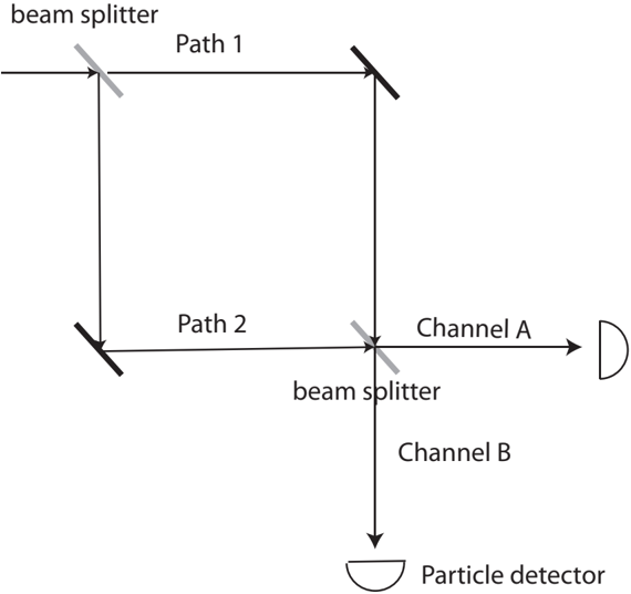
This image is a schematic diagram of a Mach-Zehnder interferometer, a classic optical setup used to demonstrate wave interference and quantum mechanical principles. The diagram illustrates the path of a beam (light or particles) as it is split, redirected by mirrors, recombined, and finally detected.
### Components/Axes
The diagram consists of the following labeled and unlabeled components:
* **Input:** An arrow entering from the left.
* **Beam Splitters:** Two gray diagonal lines.
* One is located at the top-left intersection.
* One is located at the bottom-right intersection.
* **Mirrors:** Two black diagonal lines.
* One is located at the top-right corner.
* One is located at the bottom-left corner.
* **Paths:**
* **Path 1:** The horizontal segment connecting the top-left beam splitter to the top-right mirror.
* **Path 2:** The horizontal segment connecting the bottom-left mirror to the bottom-right beam splitter.
* **Output Channels:**
* **Channel A:** The horizontal path extending to the right from the second beam splitter.
* **Channel B:** The vertical path extending downward from the second beam splitter.
* **Detectors:** Two semicircular symbols located at the ends of Channel A and Channel B. The bottom detector is explicitly labeled "Particle detector."
### Detailed Analysis
The flow of the diagram proceeds as follows:
1. **Initial Splitting:** An input beam enters from the left and strikes the top-left **beam splitter**. The beam is divided into two components.
2. **Propagation:**
* One component travels along **Path 1** (horizontally to the right) until it hits the top-right mirror, where it is reflected 90 degrees downward.
* The other component travels vertically downward from the first beam splitter until it hits the bottom-left mirror, where it is reflected 90 degrees to the right along **Path 2**.
3. **Recombination:** Both paths converge at the bottom-right **beam splitter**.
4. **Output:** The recombined beam is split again by the second beam splitter into two output channels:
* **Channel A:** Continues horizontally to the right, terminating at a detector.
* **Channel B:** Continues vertically downward, terminating at a detector labeled "Particle detector."
### Key Observations
* **Symmetry:** The diagram depicts a perfectly square configuration, implying equal path lengths for Path 1 and Path 2, which is a standard requirement for observing interference patterns in this type of interferometer.
* **Component Differentiation:** The diagram uses color coding to distinguish between optical elements: gray diagonal lines represent beam splitters, while black diagonal lines represent mirrors.
* **Labeling:** The text is placed strategically near the components they describe. "Path 1" and "Path 2" are centered above/below their respective horizontal segments.
### Interpretation
This diagram represents a fundamental experiment in quantum mechanics and optics.
* **Wave-Particle Duality:** The setup is frequently used to show that a single particle (like a photon) can effectively travel along both paths simultaneously, interfering with itself at the second beam splitter.
* **Interference:** The probability of detecting a particle in Channel A versus Channel B depends on the phase difference between the two paths. By adjusting the length of one path (or introducing a phase shift), one can control which detector "clicks."
* **Experimental Context:** The label "Particle detector" suggests this specific diagram is intended to illustrate quantum experiments (e.g., single-photon interference) rather than classical wave optics, where one might simply refer to "detectors" or "screens." The diagram demonstrates the "which-path" information problem: if you know which path the particle took, the interference pattern disappears.