## Diagram: Optical Pathway with Beam Splitters and Particle Detector
### Overview
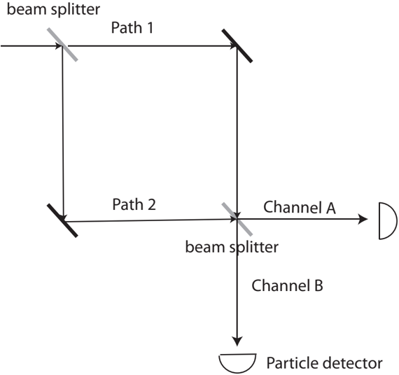
The diagram illustrates an optical system involving beam splitters, defined paths, and a particle detector. Light or particles enter from the top-left, split into two paths, recombine, and are directed to a detector via two channels.
### Components/Axes
- **Key Elements**:
- **Beam Splitter** (top-left and bottom-center).
- **Path 1**: Horizontal rightward path from the first beam splitter, then downward to the second beam splitter.
- **Path 2**: Diagonal downward-left path from the first beam splitter, then horizontal rightward to the second beam splitter.
- **Channel A**: Rightward path from the second beam splitter.
- **Channel B**: Downward path from the second beam splitter.
- **Particle Detector**: Located at the bottom-right, receiving input from Channel B.
- **Flow Direction**:
- Input enters from the top-left.
- First beam splitter divides the beam into Path 1 (right) and Path 2 (down-left).
- Path 1 and Path 2 converge at the second beam splitter.
- The second beam splitter directs portions of the beam to Channel A (right) and Channel B (down).
- Channel B terminates at the particle detector.
### Detailed Analysis
- **Beam Splitter Function**:
- The first beam splitter splits the incoming beam into two paths (Path 1 and Path 2).
- The second beam splitter recombines or further splits the beam into Channel A and Channel B.
- **Path Dynamics**:
- **Path 1**: Follows a rectangular trajectory (right → down).
- **Path 2**: Follows a diagonal trajectory (down-left → right).
- Both paths merge at the second beam splitter, suggesting interference or recombination.
- **Channel Outputs**:
- **Channel A**: Unlabeled output path (rightward), purpose unspecified.
- **Channel B**: Directly connected to the particle detector, indicating its role in measurement.
### Key Observations
1. The system uses two beam splitters to manipulate beam paths.
2. Path 2’s diagonal trajectory suggests angular redirection, possibly for interference experiments.
3. Channel B’s direct link to the detector implies it carries the signal of interest.
4. No numerical data or labels for beam intensities, angles, or detector sensitivity are provided.
### Interpretation
This diagram likely represents a simplified schematic of an interferometric or particle detection setup. The use of beam splitters and defined paths suggests applications in quantum optics, wave-particle duality experiments, or directional particle tracking. The absence of Channel A’s destination implies it may be a reference or unused output. The particle detector’s placement at the end of Channel B highlights its role as the primary measurement point.
**Note**: The diagram lacks quantitative data (e.g., beam angles, detector efficiency), limiting precise analysis of performance metrics.