## Hierarchical Diagram: System Component Structure
### Overview
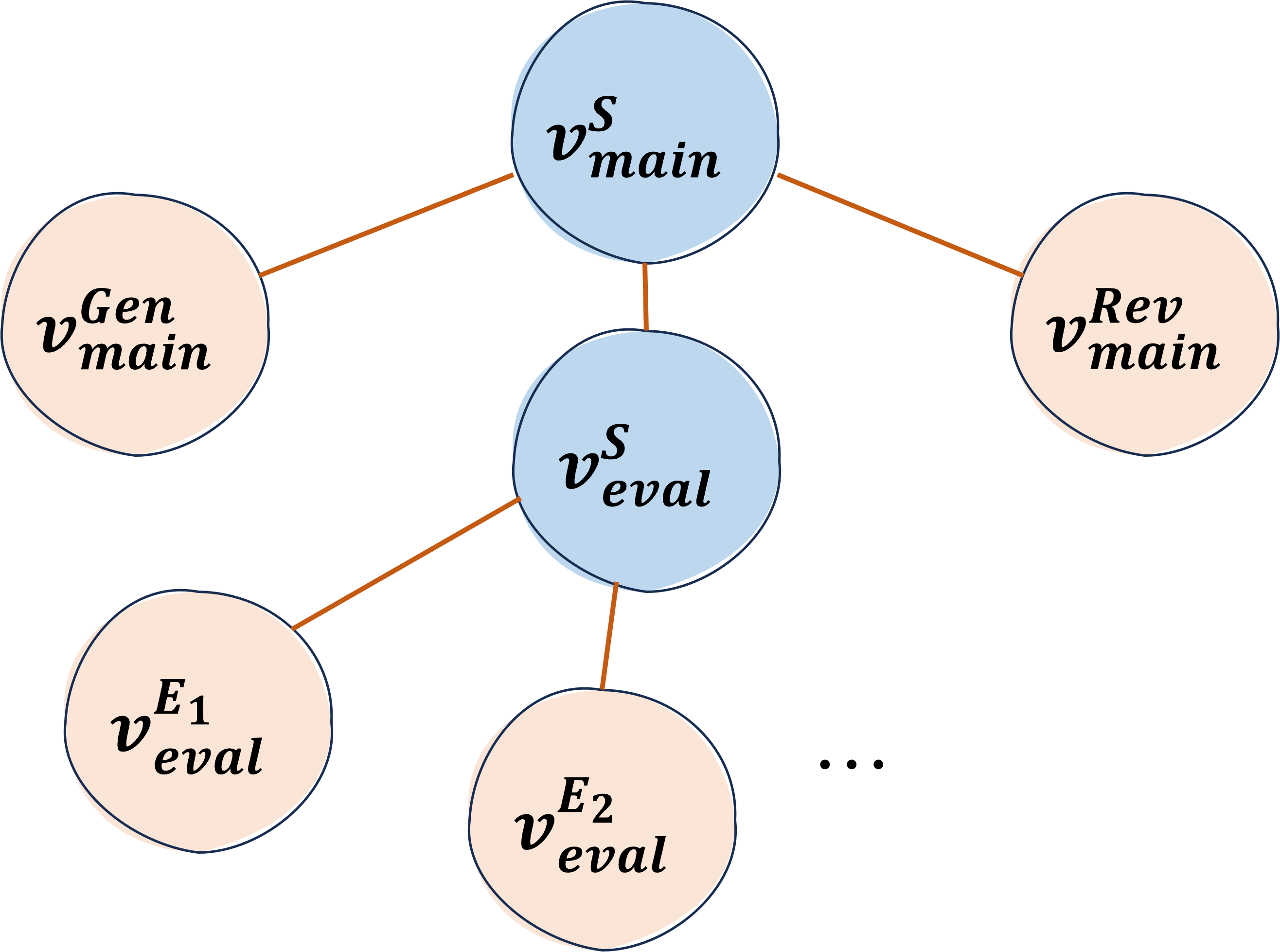
The diagram illustrates a hierarchical system architecture with three primary components: `v_main^S` (main system), `v_gen_main` (generation module), and `v_rev_main` (revision module). A secondary evaluation system (`v_eval^S`) connects to multiple evaluation instances (`v_eval^E1`, `v_eval^E2`, ...). The structure uses color-coded nodes and directional connections to represent relationships.
### Components/Axes
- **Legend**: Located at the top center, using:
- **Blue**: Represents core system components (`v_main^S`, `v_eval^S`)
- **Peach**: Denotes sub-modules (`v_gen_main`, `v_rev_main`, `v_eval^E*`)
- **Nodes**:
1. **Top Center**: `v_main^S` (main system)
2. **Left Branch**: `v_gen_main` (generation module)
3. **Right Branch**: `v_rev_main` (revision module)
4. **Central Evaluation**: `v_eval^S` (evaluation system)
5. **Evaluation Instances**:
- `v_eval^E1` (left)
- `v_eval^E2` (right)
- `...` (ellipsis indicating additional instances)
- **Connections**: Orange lines show directional relationships between nodes.
### Detailed Analysis
- **Main System (`v_main^S`)**:
- Central node with three outgoing connections
- Connects to generation (`v_gen_main`), revision (`v_rev_main`), and evaluation (`v_eval^S`) modules
- **Evaluation System (`v_eval^S`)**:
- Positioned below `v_main^S`
- Connects to multiple evaluation instances (`v_eval^E1`, `v_eval^E2`, ...)
- Subscript notation (`E1`, `E2`) suggests sequential or parallel evaluation processes
- **Sub-Modules**:
- `v_gen_main` and `v_rev_main` are terminal nodes with no further connections
- Peach coloration distinguishes them from core system components
### Key Observations
1. **Hierarchical Structure**:
- Core system (`v_main^S`) at the apex
- Sub-modules (`v_gen_main`, `v_rev_main`) at mid-level
- Evaluation system (`v_eval^S`) bridges core and instance layers
2. **Scalable Evaluation**:
- Ellipsis (`...`) indicates potential for unlimited evaluation instances
- Consistent `v_eval^E*` naming convention suggests standardized evaluation processes
3. **Color-Coded Relationships**:
- Blue nodes represent system-level components
- Peach nodes represent functional modules
- Orange connections emphasize process flow
### Interpretation
This diagram represents a modular system architecture with three key characteristics:
1. **Functional Decomposition**: The system is divided into generation, revision, and evaluation subsystems, each with distinct responsibilities.
2. **Iterative Evaluation**: The presence of multiple evaluation instances (`v_eval^E*`) suggests a quality assurance process that can scale horizontally.
3. **Centralized Control**: The `v_main^S` node acts as the system orchestrator, coordinating interactions between generation, revision, and evaluation modules.
The color coding and directional connections imply a workflow where:
- Generation (`v_gen_main`) and revision (`v_rev_main`) modules produce outputs
- These outputs are then evaluated through the `v_eval^S` system
- Multiple evaluation instances allow for parallel processing or iterative refinement
The ellipsis indicates this is a simplified representation of a potentially complex system with many evaluation stages. The lack of feedback loops suggests a linear workflow, though real-world implementations might include additional connections not shown here.