## Diagram: Matrix Operation Workflow with GPU Memory Partitioning
### Overview
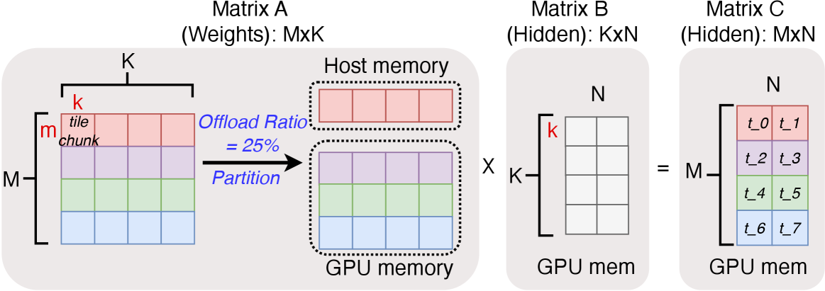
The diagram illustrates a three-stage matrix computation workflow involving host and GPU memory partitioning. It shows how matrix A (weights) is split between host and GPU memory, multiplied with matrix B (hidden) in GPU memory, and stored as matrix C (hidden) in GPU memory. Color-coded tiles represent data partitioning and computation stages.
### Components/Axes
1. **Matrix A (Weights: MxK)**
- Dimensions: M rows × K columns
- Spatial Partitioning:
- Top-left "tile chunk" (red): Host memory (25% offload ratio)
- Remaining cells (purple/green/blue): GPU memory
- Labels:
- Vertical axis: M (rows)
- Horizontal axis: K (columns)
2. **Matrix B (Hidden: KxN)**
- Dimensions: K rows × N columns
- Entirely stored in GPU memory
- Labels:
- Vertical axis: K (columns from Matrix A)
- Horizontal axis: N (columns)
3. **Matrix C (Hidden: MxN)**
- Dimensions: M rows × N columns
- Entirely stored in GPU memory
- Color-coded tiles:
- Red: t₀, t₁
- Purple: t₂, t₃
- Green: t₄, t₅
- Blue: t₆, t₇
4. **Memory Architecture**
- Host memory: Top section with red tile chunk
- GPU memory: Bottom section with partitioned matrices
5. **Legend**
- Located on the right side
- Color mapping:
- Red: "tile chunk" (host memory)
- Purple/Green/Blue: GPU memory partitions
### Detailed Analysis
- **Matrix A Partitioning**
- 25% of Matrix A (red tile chunk) remains in host memory
- 75% of Matrix A (purple/green/blue) offloaded to GPU memory
- Spatial distribution: Top-left quadrant as host memory portion
- **Matrix Multiplication Flow**
- Matrix A (GPU portion) × Matrix B (GPU) → Matrix C (GPU)
- Dimensions compatibility: (MxK) × (KxN) = (MxN)
- **Matrix C Tile Structure**
- 8 total tiles (t₀-t₇) arranged in 4 color groups
- Each color group contains 2 adjacent cells
- Tiles organized in 2x4 grid (2 columns × 4 rows)
### Key Observations
1. **Memory Optimization**
- 25% host memory retention suggests selective offloading strategy
- GPU memory handles 75% of computation-intensive data
2. **Computation Pattern**
- Tile-based processing evident in Matrix C's color-coded structure
- Suggests parallel computation across color-coded tile groups
3. **Dimensional Consistency**
- Matrix B's K dimension matches Matrix A's K dimension
- Matrix C inherits M (rows) from A and N (columns) from B
### Interpretation
This diagram demonstrates a hybrid computation strategy where:
1. **Selective Offloading**: Only 25% of weight matrix (A) remains on host, while 75% is GPU-accelerated
2. **Tile-Based Computation**: Matrix C's color-coded tiles indicate parallel processing units or computation chunks
3. **Memory Hierarchy Awareness**: Explicit distinction between host and GPU memory storage patterns
4. **Dimensional Optimization**: Matrix B's K dimension acts as a bridge between A's columns and C's rows
The workflow suggests an optimized matrix multiplication pipeline for deep learning operations, balancing host-GPU memory usage while maintaining dimensional compatibility across matrix operations. The tile-based approach in Matrix C implies potential for parallel processing across different color-coded computation units.