## Diagram: Transformation Process via Multiplication by x
### Overview
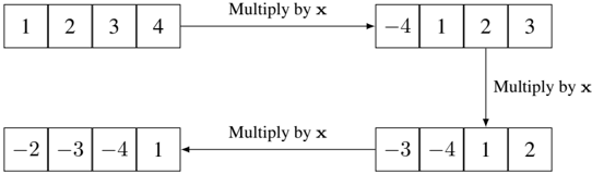
The image depicts a two-row diagram illustrating a transformation process where numerical values in boxes are modified by multiplying by a variable "x." Arrows labeled "Multiply by x" connect the boxes, indicating sequential operations. The diagram shows two distinct transformation paths: one starting with positive integers (1, 2, 3, 4) and another with negative integers (-2, -3, -4, 1).
### Components/Axes
- **Top Row**:
- Initial values: `1`, `2`, `3`, `4`
- Transformed values: `-4`, `1`, `2`, `3`
- Arrow label: "Multiply by x"
- **Bottom Row**:
- Initial values: `-2`, `-3`, `-4`, `1`
- Transformed values: `-3`, `-4`, `1`, `2`
- Arrow label: "Multiply by x"
### Detailed Analysis
- **Top Row Transformation**:
- The sequence `1 → -4`, `2 → 1`, `3 → 2`, `4 → 3` suggests a leftward cyclic shift of values, with the first element replaced by `-4`.
- Example: `1` becomes `-4`, `2` becomes `1`, `3` becomes `2`, `4` becomes `3`.
- **Bottom Row Transformation**:
- The sequence `-2 → -3`, `-3 → -4`, `-4 → 1`, `1 → 2` also follows a leftward cyclic shift, but the first element is replaced by `-3` (then `-4` in subsequent steps).
- Example: `-2` becomes `-3`, `-3` becomes `-4`, `-4` becomes `1`, `1` becomes `2`.
### Key Observations
1. **Cyclic Shift Pattern**: Both transformations involve shifting values leftward, with the first element replaced by a specific value (e.g., `-4` in the top row, `-3` in the bottom row).
2. **Consistent Labeling**: All arrows are uniformly labeled "Multiply by x," implying the same operation is applied to both rows.
3. **Value Discrepancies**: The transformed values do not align with simple multiplication (e.g., `1 * x = -4` would require `x = -4`, but `2 * x = 1` would require `x = 0.5`), suggesting the operation is not purely multiplicative.
### Interpretation
The diagram likely represents a **permutation or linear transformation** where "Multiply by x" is a simplified label for a more complex operation. The transformations suggest:
- A **cyclic permutation** of values with a modified first element.
- The variable `x` may encode a rule (e.g., `x = -1` for sign inversion, but this does not fully explain the results).
- The bottom row’s transformation introduces a **wrapping effect** (e.g., `-4 → 1`), indicating a modular or boundary condition.
The diagram emphasizes **input-output relationships** under a defined operation, though the exact mathematical definition of "Multiply by x" remains ambiguous without additional context.