## System Security Diagram: Secure Launch Process
### Overview
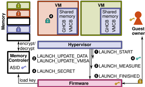
The image is a diagram illustrating a secure launch process involving a hypervisor, virtual machines (VMs), memory controller, and firmware. It depicts the flow of data and control during the launch of a VM, emphasizing security measures such as encryption, decryption, and key management.
### Components/Axes
* **Memory:** A stack of memory blocks, some with lock icons (green, red, blue).
* **VM (Virtual Machine):** Two VMs, one colored red and one colored green, each containing "Shared memory", "GHCB", and "VMCB".
* **Hypervisor:** A central component mediating access between VMs and hardware.
* **Memory Controller:** Responsible for memory encryption and decryption, associated with an "ASID" (Address Space Identifier) key.
* **Firmware:** The lowest-level software, responsible for loading keys.
* **Guest Owner:** Represents the user or entity controlling the VM.
* **Numbered Steps:** Arrows indicate the sequence of actions: 1, 2, 3, 4, 5.
* **Labels:** "encrypt/decrypt", "load key", "Shared memory", "GHCB", "VMCB", "ASID".
### Detailed Analysis
1. **Memory:**
* The memory stack consists of multiple blocks. From top to bottom:
* Top block: Green lock icon.
* Second block: Red lock icon.
* Third block: Empty block.
* Fourth block: Blue lock icon.
* Bottom block: Empty block.
* The "Memory Controller" is connected to the "Memory" stack via bidirectional arrows labeled "encrypt/decrypt".
2. **Virtual Machines (VMs):**
* Two VMs are shown: one colored red and one colored green.
* Each VM contains "Shared memory", "GHCB", and "VMCB".
* The red VM has a green lock icon labeled "4".
3. **Hypervisor:**
* The "Hypervisor" is positioned centrally.
* Arrows indicate the flow of control and data between the "Hypervisor", "Firmware", and "VMs".
4. **Memory Controller:**
* The "Memory Controller" is connected to the "Firmware" via an arrow labeled "load key".
* The "Memory Controller" has an associated "ASID" key (blue).
5. **Firmware:**
* The "Firmware" is at the bottom of the diagram.
* It has a gold key icon.
6. **Guest Owner:**
* The "Guest Owner" is on the right side of the diagram.
* An arrow points from the "Guest Owner" to the "Hypervisor".
* The "Guest Owner" has a gold key icon labeled "4".
7. **Numbered Steps:**
* **1 LAUNCH\_START:** Arrow from "Hypervisor" to "Guest Owner".
* **2 LAUNCH\_UPDATE\_DATA, LAUNCH\_UPDATE\_VMSA:** Arrow from "Memory Controller" to "Hypervisor".
* **3 LAUNCH\_MEASURE:** Arrow from "Hypervisor" to "Memory Controller".
* **4 LAUNCH\_SECRET:** Arrow from "Memory Controller" to "Hypervisor".
* **5 LAUNCH\_FINISHED:** Arrow from "Hypervisor" to "Firmware".
### Key Observations
* The diagram illustrates a secure boot or launch process for virtual machines.
* Encryption and decryption are performed by the "Memory Controller".
* The "Hypervisor" plays a central role in coordinating the launch process.
* Keys are used to secure different components and stages of the launch.
* The "Guest Owner" initiates the launch process.
### Interpretation
The diagram depicts a security-focused process for launching a virtual machine. The "Memory Controller" encrypts and decrypts memory, ensuring data confidentiality. The "Hypervisor" orchestrates the launch sequence, interacting with the "Firmware", "Memory Controller", and "VMs". The numbered steps represent a series of actions, including updating data, measuring security parameters, and exchanging secrets. The use of keys at various stages (ASID, Firmware, Guest Owner) indicates a multi-layered security approach. The diagram highlights the importance of secure boot and launch processes in virtualized environments to protect against unauthorized access and tampering.