## System Architecture Diagram: Secure Virtual Machine Launch and Memory Encryption
### Overview
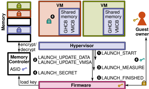
This image is a technical system architecture diagram illustrating the components and workflow for launching a secure virtual machine (VM) with hardware-assisted memory encryption. It depicts the interaction between a Guest owner, Virtual Machines (VMs), a Hypervisor, Firmware, and a Memory Controller to establish a trusted execution environment.
### Components/Axes
The diagram is organized into several key components, identified by labeled boxes and connected by directional arrows indicating data or command flow.
**Primary Components (Labeled Boxes):**
1. **Memory (Left Side):** A vertical stack of colored blocks representing memory regions. From top to bottom:
* Green block with a lock icon.
* Orange block with a lock icon.
* White block.
* Blue block with a lock icon.
* White block.
* A double-headed arrow labeled **"encrypt/decrypt"** connects this stack to the "Memory Controller".
2. **Memory Controller (Bottom Left):** A white box containing the text **"Memory Controller"** and **"ASID"** with a key icon. An arrow labeled **"load key"** points from the "Firmware" to this component.
3. **VM (Top Center & Right):** Two large boxes labeled **"VM"**.
* The left VM (salmon-colored) contains a blue box labeled **"Shared memory"** with sub-labels **"GHCB"** and **"VMCB"**. A lock icon with the number **"4"** is attached to this shared memory box.
* The right VM (light green) contains an identical blue "Shared memory" box with "GHCB" and "VMCB".
4. **Guest owner (Top Right):** Represented by a red person icon. A key icon is shown next to it.
5. **Hypervisor (Center):** A wide, light blue box labeled **"Hypervisor"**. It is the central hub for command flow.
6. **Firmware (Bottom Center):** A pink box labeled **"Firmware"**. A key icon is attached to it.
**Command Flow (Numbered Arrows):**
A sequence of numbered arrows defines the launch protocol, primarily flowing between the Hypervisor and Firmware:
* **1:** Arrow from Hypervisor to Firmware, labeled **"LAUNCH_START"**.
* **2:** Arrow from Hypervisor to Firmware, labeled **"LAUNCH_MEASURE"**.
* **3:** Arrow from Hypervisor to Firmware, labeled **"LAUNCH_FINISHED"**.
* **4:** Arrow from Guest owner to the left VM's shared memory (indicating a measurement or attestation step).
* **5:** Arrow from Firmware to Hypervisor, labeled **"LAUNCH_UPDATE_DATA"** and **"LAUNCH_UPDATE_VMSA"**.
* **6:** Arrow from Firmware to Hypervisor, labeled **"LAUNCH_SECRET"**.
### Detailed Analysis
The diagram outlines a multi-step, secure VM instantiation process:
1. **Initialization & Key Loading:** The process begins with the **Firmware** loading an encryption key into the **Memory Controller** (arrow: "load key"). The Memory Controller is responsible for the **"encrypt/decrypt"** operations on the main **Memory** stack.
2. **Launch Sequence Initiation:** The **Hypervisor** initiates the launch by sending a **"LAUNCH_START"** command (1) to the Firmware.
3. **Measurement & Attestation:** The Hypervisor then requests a measurement via **"LAUNCH_MEASURE"** (2). This measurement likely involves the **Guest owner** (4) interacting with the **Shared memory (GHCB/VMCB)** of the target VM to establish a hardware root of trust.
4. **Secret Provisioning & Configuration:** The Firmware responds by sending **"LAUNCH_UPDATE_DATA"** and **"LAUNCH_UPDATE_VMSA"** (5) back to the Hypervisor, likely providing the measured boot data and virtual machine control structures. It also sends a **"LAUNCH_SECRET"** (6), which could be an attestation report or a derived key.
5. **Completion:** The Hypervisor signals the end of the process with **"LAUNCH_FINISHED"** (3).
6. **Runtime State:** The two **VMs** are shown in a running state, each with their own **Shared memory** region containing a **Guest-VM Communication Block (GHCB)** and a **Virtual Machine Control Block (VMCB)**. The lock icon (4) on the left VM's shared memory suggests it is in a measured/secure state.
### Key Observations
* **Central Role of Firmware:** The Firmware acts as a trusted platform module (TPM) or secure enclave, managing secrets (keys) and performing measurements.
* **Hardware-Assisted Security:** The direct link between the Memory Controller and physical Memory, with explicit "encrypt/decrypt" operations, indicates hardware-based memory encryption (e.g., AMD SEV or Intel TDX).
* **Shared Memory Communication:** The GHCB and VMCB are standard components for hypervisor-guest communication in confidential computing architectures.
* **Asymmetric Flow:** The command flow is primarily Hypervisor-driven, with Firmware acting as a secure co-processor that validates and provisions secrets.
### Interpretation
This diagram details the **secure launch flow for a confidential virtual machine**. It demonstrates a hardware-rooted chain of trust where:
1. The **Firmware** is the root of trust, holding the platform keys.
2. The **Hypervisor** orchestrates the launch but does not have direct access to secrets.
3. **Memory encryption** is enforced by a dedicated controller, protecting VM data even from a compromised hypervisor.
4. The **Guest owner** can verify the integrity of the VM through the measurement process (step 4), ensuring the VM is running on genuine, up-to-date hardware before releasing secrets to it.
The overall purpose is to enable **multi-tenant cloud environments** where a cloud provider (operating the hypervisor) can host workloads for a guest owner without being able to inspect or tamper with the guest's memory contents. The "Shared memory" with GHCB/VMCB is the secure communication channel that makes this isolation possible. The numbered steps (1-6) represent the critical attestation and key provisioning handshake that must succeed before the VM can be considered secure and operational.