## [Diagram]: System Flow and State Transition Logic
### Overview
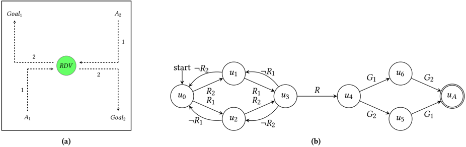
The image presents two distinct diagrams labeled (a) and (b).
- **Diagram (a)** is a high-level schematic illustrating a central "RDV" (Rendezvous) node interacting with four peripheral nodes ($A_1$, $A_2$, $Goal_1$, $Goal_2$).
- **Diagram (b)** is a formal state transition diagram (a finite state machine) depicting the logical progression from a "start" state through various intermediate states ($u_0$ to $u_6$) to a final state ($u_A$).
---
### Components/Axes
#### Diagram (a)
* **Central Node:** A green circle labeled "RDV".
* **Peripheral Nodes:**
* **Top-Left:** $Goal_1$
* **Top-Right:** $A_2$
* **Bottom-Left:** $A_1$
* **Bottom-Right:** $Goal_2$
* **Flow Indicators:** Dashed lines with arrows indicating direction, labeled with numerical values "1" or "2".
#### Diagram (b)
* **Nodes:** Circular nodes labeled $u_0, u_1, u_2, u_3, u_4, u_5, u_6, u_A$.
* **Final State:** $u_A$ is represented by a double-circle, indicating it is the terminal or accepting state.