## Diagram: LLM-Based Python Code Generation Process Flow
### Overview
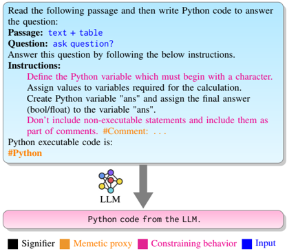
The image is a technical flowchart diagram illustrating a structured process for using a Large Language Model (LLM) to generate Python code from a given text passage and question. The diagram uses color-coded elements and directional arrows to define inputs, constraints, and the processing flow.
### Components/Axes
The diagram is composed of three primary vertical sections connected by downward-pointing arrows, with a legend at the bottom.
1. **Top Section (Input & Instructions Box):**
* A rectangular box with a light blue background and a darker blue border.
* **Text Content (Transcribed):**
```
Read the following passage and then write Python code to answer the question:
Passage: text + table
Question: ask question?
Answer this question by following the below instructions.
Instructions:
Define the Python variable which must begin with a character.
Assign values to variables required for the calculation.
Create Python variable "ans" and assign the final answer (bool/float) to the variable "ans".
Don't include non-executable statements and include them as part of the comments. #Comment: ...
Python executable code is:
#Python
```
* **Color Coding:** The text "Instructions:" and the subsequent instruction lines are in **pink**. The text "Passage:", "Question:", and "Python executable code is:" are in **blue**. The example comment `#Comment: ...` is in **pink**.
2. **Middle Section (LLM Icon):**
* A stylized icon representing a neural network or LLM, labeled "LLM" below it.
* The icon consists of interconnected nodes in various colors (blue, orange, pink, black).
3. **Bottom Section (Output Box):**
* A rectangular box with a pink background and a darker pink border.
* **Text Content (Transcribed):** `Python code from the LLM.`
4. **Legend (Bottom of Image):**
* A horizontal legend with four color-coded categories.
* **Categories and Labels:**
* **Black Square:** Signifier
* **Orange Square:** Memetic proxy
* **Pink Square:** Constraining behavior
* **Blue Square:** Input
### Detailed Analysis
* **Flow Direction:** The process flows vertically from top to bottom, indicated by two thick, gray, downward-pointing arrows.
1. Arrow 1: From the bottom of the "Input & Instructions" box to the top of the "LLM" icon.
2. Arrow 2: From the bottom of the "LLM" icon to the top of the "Output" box.
* **Color-Element Mapping (Cross-Referenced with Legend):**
* **Blue (Input):** Corresponds to the core input elements in the top box: the `Passage`, the `Question`, and the prompt to generate `Python executable code`.
* **Pink (Constraining behavior):** Corresponds to the `Instructions` section and the example `#Comment`. This color also defines the final output box, suggesting the output is a direct result of the constrained process.
* **Orange (Memetic proxy) & Black (Signifier):** These colors appear within the LLM icon's node network but are not explicitly mapped to specific text or structural elements in the flowchart itself. They likely represent internal components or concepts within the LLM's processing.
* **Spatial Grounding:** The legend is positioned at the very bottom, centered. The main process flow is centered horizontally. The "Input & Instructions" box occupies the top ~40% of the diagram's height. The "LLM" icon is in the center. The "Output" box is at the bottom.
### Key Observations
1. **Structured Constraint Emphasis:** The diagram heavily emphasizes the "Instructions" (pink) as the governing rules for the code generation task, separating them visually from the raw input data (blue).
2. **Process Abstraction:** The LLM is represented as a single, opaque processing unit ("black box") between defined input and output, with its internal complexity hinted at by the multi-colored network icon.
3. **Output Definition:** The final output is not just "code," but specifically "Python code from the LLM," generated under the given constraints.
### Interpretation
This diagram models a **constrained text-to-code generation pipeline**. It demonstrates a method to improve the reliability and specificity of LLM outputs by providing explicit, structured instructions alongside the raw data (passage and question).
* **Relationship Between Elements:** The blue "Input" provides the *what* (data and task), while the pink "Constraining behavior" defines the *how* (syntactic and structural rules). The LLM acts as the translator between these two domains, producing an output that adheres to the constraints.
* **Underlying Principle:** The color coding suggests a framework for analyzing prompts. Effective prompts for code generation should clearly delineate input data (blue) from executable constraints (pink). The "Memetic proxy" (orange) and "Signifier" (black) may refer to the LLM's internal representation of concepts and symbols, respectively, which are necessary for it to understand and execute the task.
* **Practical Implication:** This approach aims to mitigate common LLM failure modes in coding tasks, such as generating explanatory text alongside code or using incorrect variable naming conventions, by baking those requirements directly into the prompt structure. The diagram serves as a blueprint for designing such prompts.