## Diagram: One Model vs. Many Models Architecture
### Overview
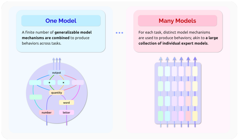
The image compares two conceptual approaches to model design: a unified "One Model" system and a distributed "Many Models" system. Both are illustrated with diagrams showing component relationships and data flow.
### Components/Axes
**Left Section ("One Model"):**
- **Title Box**: Blue rectangle with "One Model" in dark blue text
- **Text Paragraph**: Describes combining generalizable model mechanisms to produce behaviors across tasks
- **Diagram**:
- Central purple circle labeled "output"
- Internal components:
- "quantity" (central node)
- "word" (connected to quantity)
- "number" (connected to quantity)
- "letter" (connected to quantity)
- Operations:
- "+" (addition) between quantity and word
- "×" (multiplication) between quantity and number
- Arrows: Multiple upward-pointing arrows from the circle
**Right Section ("Many Models"):**
- **Title Box**: Pink rectangle with "Many Models" in dark red text
- **Text Paragraph**: Describes using distinct model mechanisms per task, akin to expert models
- **Diagram**:
- Grid of 12 colored rectangles (3 rows × 4 columns)
- Colors: Green, blue, pink, yellow
- Arrows: Each rectangle has an upward-pointing arrow
- Output: Implied connection to all rectangles
### Detailed Analysis
**One Model Diagram:**
- Circular architecture suggests integrated processing
- Mathematical operations (+, ×) indicate computational relationships
- Components represent different data types (words, numbers, letters)
- Output node acts as central processing unit
**Many Models Diagram:**
- Grid structure implies modular, task-specific components
- Color variation may represent different model types or task categories
- Uniform upward arrows suggest parallel processing paths
### Key Observations
1. **Architectural Contrast**: Circular integration vs. grid-based modularity
2. **Data Flow**: Both systems show output as terminal node, but with different input relationships
3. **Complexity**: One Model shows fewer components with explicit operations, Many Models shows more components with implied specialization
4. **Color Coding**: Many Models uses distinct colors for components, suggesting categorical differentiation
### Interpretation
This diagram illustrates fundamental approaches to AI/ML system design:
- **One Model** represents generalist architectures where a single system handles multiple tasks through combined mechanisms (e.g., transformer models with shared attention)
- **Many Models** represents specialist architectures where separate models handle specific tasks (e.g., ensemble methods or modular neural networks)
The mathematical operations in the One Model suggest explicit computational relationships between components, while the Many Models' grid implies parallel processing capabilities. The color coding in Many Models might indicate different model families or task categories, though this isn't explicitly stated.
The diagrams emphasize different tradeoffs: One Model prioritizes parameter efficiency and cross-task generalization, while Many Models emphasizes task-specific optimization at potential computational cost.