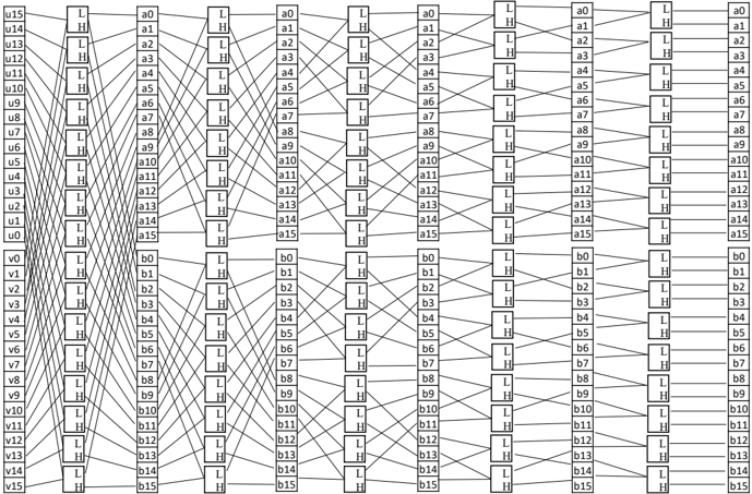
## Logic Diagram: Butterfly Network
### Overview
The image depicts a butterfly network, a multi-stage interconnection network commonly used in parallel computing and telecommunications. The diagram illustrates the flow of data through the network, with inputs on the left and outputs on the right. The network consists of multiple stages of switching elements, each of which can either pass the input straight through or swap the two inputs.
### Components/Axes
* **Inputs (Left)**:
* `u0` to `u15` (16 inputs)
* `v0` to `v15` (16 inputs)
* **Outputs (Right)**:
* `a0` to `a15` (16 outputs)
* `b0` to `b15` (16 outputs)
* **Switching Elements**: Rectangular boxes with two inputs and two outputs. Each box has two states, indicated by "L" and "H".
* "L": Lower input connects to the lower output, upper input connects to the upper output (straight-through).
* "H": Lower input connects to the upper output, upper input connects to the lower output (swap).
* **Stages**: The network consists of multiple stages of switching elements. There are 6 stages in total.
* **Connections**: Lines connecting the inputs, switching elements, and outputs.
### Detailed Analysis
The diagram shows the interconnection pattern of a butterfly network. The inputs `u0` to `u15` and `v0` to `v15` are fed into the first stage of switching elements. Each switching element either passes the inputs straight through (L state) or swaps them (H state). The outputs of the first stage are then fed into the second stage, and so on, until the final stage produces the outputs `a0` to `a15` and `b0` to `b15`.
The specific connections and switching element states determine the overall behavior of the network. The diagram shows a particular configuration of the network, but other configurations are possible.
Here's a breakdown of the connections and switch states at each stage:
**Stage 1:**
* Inputs `u0` to `u15` and `v0` to `v15` are connected to the first stage of switching elements.
* The switch states alternate between "L" and "H" for each pair of inputs.
* `u15` connects to a switch set to "L"
* `u14` connects to a switch set to "H"
* `u13` connects to a switch set to "L"
* `u12` connects to a switch set to "H"
* `u11` connects to a switch set to "L"
* `u10` connects to a switch set to "H"
* `u9` connects to a switch set to "L"
* `u8` connects to a switch set to "H"
* `u7` connects to a switch set to "L"
* `u6` connects to a switch set to "H"
* `u5` connects to a switch set to "L"
* `u4` connects to a switch set to "H"
* `u3` connects to a switch set to "L"
* `u2` connects to a switch set to "H"
* `u1` connects to a switch set to "L"
* `u0` connects to a switch set to "H"
* `v0` connects to a switch set to "L"
* `v1` connects to a switch set to "H"
* `v2` connects to a switch set to "L"
* `v3` connects to a switch set to "H"
* `v4` connects to a switch set to "L"
* `v5` connects to a switch set to "H"
* `v6` connects to a switch set to "L"
* `v7` connects to a switch set to "H"
* `v8` connects to a switch set to "L"
* `v9` connects to a switch set to "H"
* `v10` connects to a switch set to "L"
* `v11` connects to a switch set to "H"
* `v12` connects to a switch set to "L"
* `v13` connects to a switch set to "H"
* `v14` connects to a switch set to "L"
* `v15` connects to a switch set to "H"
**Stages 2-6:**
* The connections between stages become more complex, with each input potentially connecting to multiple outputs depending on the switch states.
* The switch states in each stage are arranged in a specific pattern to achieve the desired interconnection properties of the butterfly network.
* The switch states alternate between "L" and "H" for each pair of inputs.
**Outputs:**
* The outputs of the final stage are `a0` to `a15` and `b0` to `b15`.
* The specific mapping between inputs and outputs depends on the configuration of the network.
### Key Observations
* The butterfly network is a multi-stage network with a regular interconnection pattern.
* The switching elements in the network can either pass the inputs straight through or swap them.
* The specific connections and switch states determine the overall behavior of the network.
### Interpretation
The butterfly network is a versatile interconnection network that can be used for a variety of applications. It is particularly well-suited for parallel computing, where it can be used to connect processors to memory or to other processors. The network's regular interconnection pattern makes it relatively easy to implement in hardware. The butterfly network is a fundamental building block in many parallel computing systems.