## Diagram: Signal Routing Network Schematic
### Overview
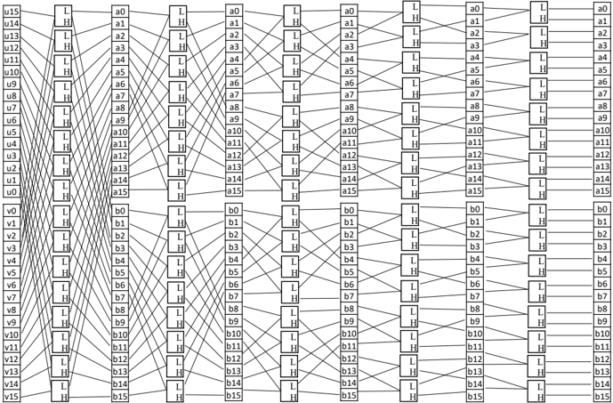
The image displays a complex technical schematic diagram representing a signal routing or switching network. It consists of a grid of rectangular blocks connected by a dense network of lines, illustrating the interconnections between input signals (left side) and output signals (right side) through intermediate switching elements. The diagram is purely structural, with no numerical data, charts, or graphs.
### Components/Axes
* **Left Side (Inputs):** Two vertical columns of labels.
* Top column: Labels `u15` (top) down to `u0` (bottom).
* Bottom column: Labels `v15` (top) down to `v0` (bottom).
* **Right Side (Outputs):** Two vertical columns of labels.
* Top column: Labels `a0` (top) down to `a15` (bottom).
* Bottom column: Labels `b0` (top) down to `b15` (bottom).
* **Central Grid (Switching Elements):** The core of the diagram is a grid of rectangular blocks arranged in multiple vertical columns. Each block contains two vertically stacked letters: an "L" (top) and an "H" (bottom). These likely represent "Low" and "High" signal states or logic levels.
* **Interconnections:** A complex web of lines connects the input labels on the left to the blocks in the central grid, and from those blocks to the output labels on the right. The lines cross over each other in a structured, non-random pattern.
### Detailed Analysis
* **Structure:** The diagram is organized into three main vertical sections: Inputs (left), Switching Matrix (center), and Outputs (right).
* **Connection Pattern:**
* Each input label (`u0-u15`, `v0-v15`) has a line connecting it to a specific block in the first column of the central grid.
* Lines then connect blocks between adjacent columns within the central grid.
* Finally, lines connect blocks in the last column of the central grid to the output labels (`a0-a15`, `b0-b15`).
* **Block Function:** Each "L/H" block appears to be a node or switch point where signals can be routed. The specific pattern of connections defines the network's function.
* **Spatial Grounding:** The input labels are positioned along the far-left edge. The output labels are positioned along the far-right edge. The switching matrix occupies the entire central area. The connections form a symmetrical, crisscrossing pattern that is denser in the middle.
### Key Observations
* **Symmetry:** The connection pattern exhibits a high degree of symmetry. The routing for the top half (`u` inputs to `a` outputs) mirrors the pattern for the bottom half (`v` inputs to `b` outputs).
* **Structured Permutation:** The lines do not connect inputs to outputs directly. Instead, they follow a specific, repeating permutation pattern through the grid of "L/H" blocks, characteristic of a multistage interconnection network (MIN) like a butterfly or omega network.
* **No Numerical Data:** The diagram contains no quantitative data, axes, scales, or legends with numerical values. It is a purely qualitative schematic of connections.
### Interpretation
This diagram illustrates the architecture of a **multistage interconnection network (MIN)**, commonly used in parallel computing, telecommunications, and switching systems. Its purpose is to route signals from a set of inputs to a set of outputs.
* **What it demonstrates:** The network allows any input (`u` or `v`) to potentially connect to any output (`a` or `b`) by setting the appropriate paths through the stages of "L/H" switches. The specific wiring pattern defines the network's connectivity properties, such as whether it is a blocking or non-blocking network.
* **Relationship between elements:** The inputs are the sources, the outputs are the destinations, and the central grid of "L/H" blocks represents the programmable or fixed switching elements that establish the paths. The lines represent the physical or logical communication channels.
* **Notable Pattern:** The intricate, symmetrical crisscrossing of lines is not arbitrary. It represents a specific mathematical permutation function designed to provide efficient and often non-blocking connectivity between inputs and outputs with a minimal number of switching stages. This type of network is fundamental to the design of high-performance routers, parallel processor interconnects, and telephone exchange systems.
**Language Declaration:** All text in the image is in English (using the Latin alphabet). No other languages are present.