## Diagram: Splice Operations
### Overview
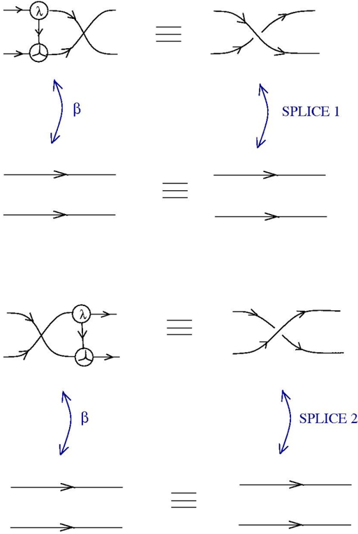
The image illustrates two splice operations (Splice 1 and Splice 2) using diagrammatic representations. Each operation shows an equivalence between a complex network of lines and nodes and a simpler representation involving crossing lines. The operations are linked by a transformation labeled "β".
### Components/Axes
* **Nodes:** Circular nodes with internal symbols (λ in the top node, a three-pronged symbol in the bottom node).
* **Lines:** Lines with arrows indicating direction.
* **Equivalence Symbol:** "≡" (three horizontal lines).
* **Transformation Arrow:** Curved arrow labeled "β".
* **Splice Labels:** "SPLICE 1" and "SPLICE 2" with curved arrows.
### Detailed Analysis
**Splice 1 (Top Half):**
1. **Left Side:** A complex network of lines. Two lines enter a node containing "λ" at the top. A line exits this node and connects to a node containing a three-pronged symbol. Two lines exit the three-pronged node. The top line crosses over the bottom line.
2. **Equivalence:** The complex network is equivalent to a simple crossing of two lines.
3. **Transformation:** A curved arrow labeled "β" points downwards from the complex network to two parallel lines with arrows indicating direction.
4. **Result:** The crossing of lines is equivalent to two parallel lines with arrows indicating direction.
5. **Splice Label:** A curved arrow labeled "SPLICE 1" points downwards from the crossing of lines to two parallel lines with arrows indicating direction.
**Splice 2 (Bottom Half):**
1. **Left Side:** A complex network of lines. Two lines enter a node containing "λ" at the top. A line exits this node and connects to a node containing a three-pronged symbol. Two lines exit the three-pronged node. The bottom line crosses over the top line.
2. **Equivalence:** The complex network is equivalent to a simple crossing of two lines.
3. **Transformation:** A curved arrow labeled "β" points downwards from the complex network to two parallel lines with arrows indicating direction.
4. **Result:** The crossing of lines is equivalent to two parallel lines with arrows indicating direction.
5. **Splice Label:** A curved arrow labeled "SPLICE 2" points downwards from the crossing of lines to two parallel lines with arrows indicating direction.
### Key Observations
* Both Splice 1 and Splice 2 involve a transformation from a complex network to a simpler crossing of lines.
* The transformation "β" simplifies the complex network to parallel lines.
* The only difference between Splice 1 and Splice 2 is the order in which the lines cross (top over bottom vs. bottom over top).
### Interpretation
The diagram illustrates how complex network structures can be simplified through splice operations. The "β" transformation represents a key step in this simplification process, reducing the network to parallel lines. The difference between Splice 1 and Splice 2 highlights how the order of line crossings can be significant in these operations. The diagram likely represents a step in a larger process of network simplification or manipulation, possibly within the context of theoretical physics or mathematics.