## Diagram: Hierarchical Network Structure
### Overview
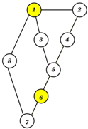
The image depicts a hierarchical network diagram with 8 nodes (labeled 1–8) connected by directed edges. Two nodes (1 and 6) are highlighted in yellow, suggesting a distinction from the others. The structure resembles a decision tree or organizational chart with branching paths.
### Components/Axes
- **Nodes**: Labeled 1–8, with no explicit axis titles or scales.
- **Edges**: Directed connections between nodes, forming a tree-like hierarchy.
- **Legend**: Yellow color coding for nodes 1 and 6 (no explicit legend box, inferred from visual emphasis).
- **Flow Direction**: Top-to-bottom and left-to-right branching, with no cyclical paths.
### Detailed Analysis
- **Node 1** (top-left, yellow): Root node with two outgoing edges to nodes 2 and 3.
- **Node 2** (top-right): Connected only to node 1.
- **Node 3** (middle-left): Branches to nodes 5 and 8.
- **Node 4** (middle-right): Connected to node 5.
- **Node 5** (center): Branches to nodes 6 and 4.
- **Node 6** (bottom-center, yellow): Connected to node 5 and node 7.
- **Node 7** (bottom-left): Connected only to node 6.
- **Node 8** (bottom-right): Connected only to node 3.
### Key Observations
1. **Hierarchical Structure**: The diagram follows a strict top-down hierarchy with no loops or feedback paths.
2. **Critical Nodes**: Nodes 1 and 6 are highlighted in yellow, potentially indicating priority, decision points, or bottlenecks.
3. **Branching Complexity**: Node 5 has the highest out-degree (2), suggesting it is a pivotal junction.
4. **Terminal Nodes**: Nodes 2, 4, 7, and 8 have no outgoing edges, acting as endpoints.
### Interpretation
The diagram likely represents a decision-making process, organizational workflow, or network topology. The yellow-highlighted nodes (1 and 6) may denote starting/ending points or critical decision nodes. The absence of numerical values or quantitative data suggests the focus is on structural relationships rather than measurable metrics. The branching pattern implies multiple possible paths, with node 5 serving as a convergence point for multiple sub-branches. The lack of cyclical connections indicates a linear progression through the system.