## Diagram: LLM Agent Architecture with SLM Tool Calling
### Overview
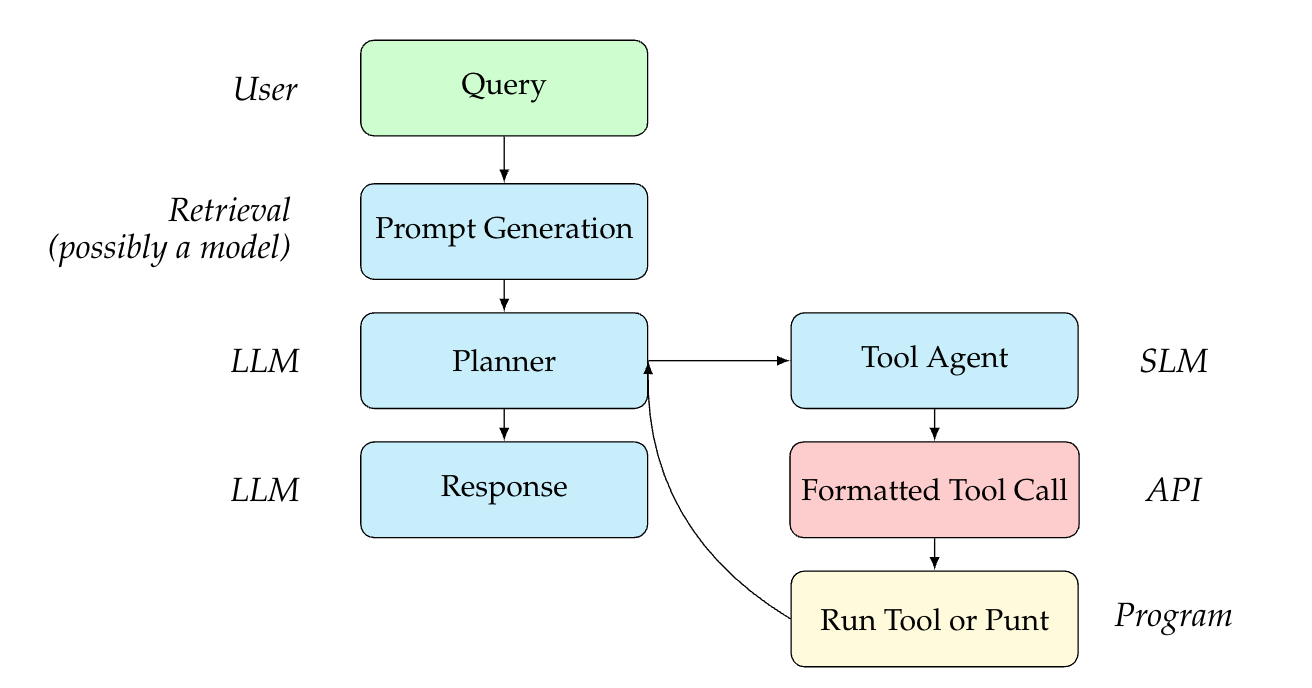
This image is a technical flowchart illustrating a system architecture for an AI agent. It details the process flow from receiving a user query to generating a final response, highlighting the orchestration between Large Language Models (LLMs), Small Language Models (SLMs), retrieval systems, and external programmatic tools. The diagram uses color-coded rectangular nodes with rounded corners and directional arrows to indicate the sequence of operations.
*Note: As this is a structural flowchart, there are no numerical data points, axes, or charts present.*
### Components and Spatial Layout
The diagram is spatially organized into two main vertical columns: a primary execution flow on the left, and a secondary tool-calling loop on the right. Text labels are positioned to the left or right of the nodes to indicate the actor, technology, or system responsible for that specific step.
**Left Column (Primary Flow - Top to Bottom):**
1. **Actor Label:** *User* (Positioned top-left)
* **Node:** `Query` (Color: Light Green)
2. **Actor Label:** *Retrieval (possibly a model)* (Positioned mid-left)
* **Node:** `Prompt Generation` (Color: Light Blue)
3. **Actor Label:** *LLM* (Positioned mid-left)
* **Node:** `Planner` (Color: Light Blue)
4. **Actor Label:** *LLM* (Positioned bottom-left)
* **Node:** `Response` (Color: Light Blue)
**Right Column (Tool Loop - Top to Bottom, branching from Planner):**
1. **Actor Label:** *SLM* (Positioned mid-right)
* **Node:** `Tool Agent` (Color: Light Blue)
2. **Actor Label:** *API* (Positioned mid-right)
* **Node:** `Formatted Tool Call` (Color: Light Pink/Red)
3. **Actor Label:** *Program* (Positioned bottom-right)
* **Node:** `Run Tool or Punt` (Color: Light Yellow)
### Content Details (Process Flow)
The directional arrows dictate the logical progression of the system:
1. **Initial Input:** The flow begins at the top left with the `Query` node.
2. **Contextualization:** A downward arrow connects `Query` to `Prompt Generation`. The label indicates this step involves "Retrieval," suggesting a Retrieval-Augmented Generation (RAG) process to build the prompt.
3. **Orchestration:** A downward arrow connects `Prompt Generation` to the `Planner`. The `Planner` acts as the central routing hub of the architecture.
4. **Branching Logic:** From the `Planner`, the flow can take two distinct paths:
* **Path A (Completion):** A downward arrow leads directly from `Planner` to `Response`. This indicates the LLM has enough information to answer the user.
* **Path B (Tool Execution):** A rightward arrow leads from `Planner` to `Tool Agent`.
5. **Tool Execution Sequence:**
* A downward arrow connects `Tool Agent` to `Formatted Tool Call`.
* A downward arrow connects `Formatted Tool Call` to `Run Tool or Punt`.
6. **Feedback Loop:** A curved arrow originates from the left side of the `Run Tool or Punt` node and points upwards and leftwards, terminating back at the `Planner` node.
### Key Observations
* **Separation of Model Sizes:** The architecture explicitly separates the roles of an LLM (Large Language Model) and an SLM (Small Language Model). The LLM handles high-level tasks (`Planner`, `Response`), while the SLM is dedicated to a narrow task (`Tool Agent`).
* **The Orchestration Loop:** The curved arrow creates a distinct "While" loop. The `Planner` can continuously route to the `Tool Agent`, execute a tool, receive the result, and plan the next step until it decides to break the loop and move to `Response`.
* **Color Coding:** While not explicitly defined in a legend, colors appear to group functions: Green for input, Blue for neural model processing (Prompt Gen, Planner, Response, Tool Agent), Pink for structured data formatting (API call), and Yellow for external execution.
### Interpretation
This diagram outlines a highly optimized, agentic AI workflow—likely a variation of the ReAct (Reasoning and Acting) framework.
By reading between the lines, the explicit use of an **SLM** for the `Tool Agent` is the most critical architectural decision shown here. In traditional agentic frameworks, a massive, computationally expensive LLM is used to decide which tool to use and how to format the JSON/API request. By offloading the specific task of formatting tool calls to a smaller, faster, and cheaper SLM, the system designers are optimizing for lower latency and reduced inference costs.
The `Planner` (the LLM) acts as the "brain." It receives the augmented prompt, decides *if* a tool is needed, and passes the intent to the SLM. The SLM translates that intent into a `Formatted Tool Call` for an API. The external `Program` runs it, and the result is fed back to the LLM `Planner`. The inclusion of the word "Punt" in the execution node suggests a built-in error handling or fallback mechanism—if a tool fails or the request is invalid, the system "punts" the error back to the Planner to re-evaluate, rather than crashing the entire application. Ultimately, once the Planner has gathered sufficient data through this loop, it synthesizes the final `Response`.