## Diagram: LLM Tool Use Flow
### Overview
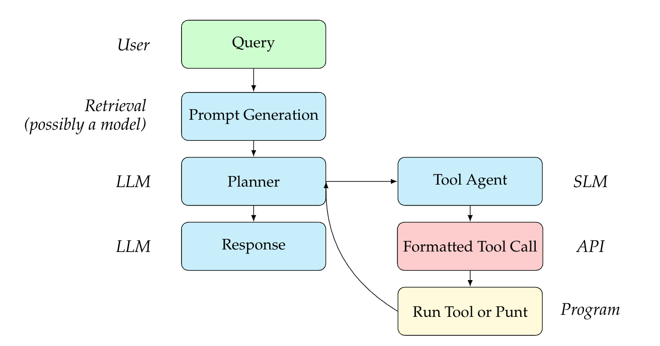
The image is a flowchart illustrating the process of how a Large Language Model (LLM) interacts with tools to fulfill a user query. The diagram outlines the steps from the initial user query to the execution of a tool or a direct response.
### Components/Axes
* **Nodes:** The diagram consists of rounded rectangle nodes representing different stages or components in the process.
* **Edges:** Arrows indicate the flow of information or control between the nodes.
* **Labels:** Each node is labeled with a description of its function.
* **Color Coding:**
* Green: User input
* Light Blue: LLM-related processes
* Light Red: API interaction
* Light Yellow: Program execution
* **Side Labels:**
* User: Indicates the source of the initial query.
* Retrieval (possibly a model): Describes the prompt generation stage.
* LLM: Indicates stages involving the Large Language Model.
* SLM: Indicates the stage involving the Small Language Model.
* API: Indicates the stage involving the Application Programming Interface.
* Program: Indicates the stage involving program execution.
### Detailed Analysis
1. **User:**
* **Query:** The process begins with a user submitting a query. The node is located at the top-left of the diagram and is colored green.
2. **Retrieval (possibly a model):**
* **Prompt Generation:** The query is used to generate a prompt. This node is light blue and is directly below the "Query" node.
3. **LLM:**
* **Planner:** The prompt is fed into the LLM, which acts as a planner. This node is light blue and is below the "Prompt Generation" node.
* **Response:** The LLM generates a response. This node is light blue and is below the "Planner" node.
4. **SLM:**
* **Tool Agent:** The planner interacts with a tool agent. This node is light blue and is to the right of the "Planner" node.
5. **API:**
* **Formatted Tool Call:** The tool agent formats a tool call. This node is light red and is below the "Tool Agent" node.
6. **Program:**
* **Run Tool or Punt:** The formatted tool call is used to run a tool, or the process punts (returns to the LLM). This node is light yellow and is below the "Formatted Tool Call" node.
7. **Feedback Loop:** An arrow connects the "Run Tool or Punt" node back to the "Planner" node, indicating a feedback loop.
### Key Observations
* The diagram illustrates a sequential process with a feedback loop.
* The LLM acts as a central component, responsible for planning and generating responses.
* The tool agent facilitates interaction with external tools.
* The color coding helps to distinguish between different types of processes.
### Interpretation
The diagram depicts a system where a user query is processed by an LLM, which can leverage external tools to generate a response. The LLM acts as a planner, deciding whether to use a tool or respond directly. If a tool is needed, the tool agent formats the call, and the tool is executed. The results of the tool execution are then fed back into the LLM, allowing it to refine its response. This process highlights the ability of LLMs to integrate with external tools to enhance their capabilities. The feedback loop suggests an iterative process where the LLM can learn and improve its tool usage over time.