\n
## Diagram: Agent Workflow
### Overview
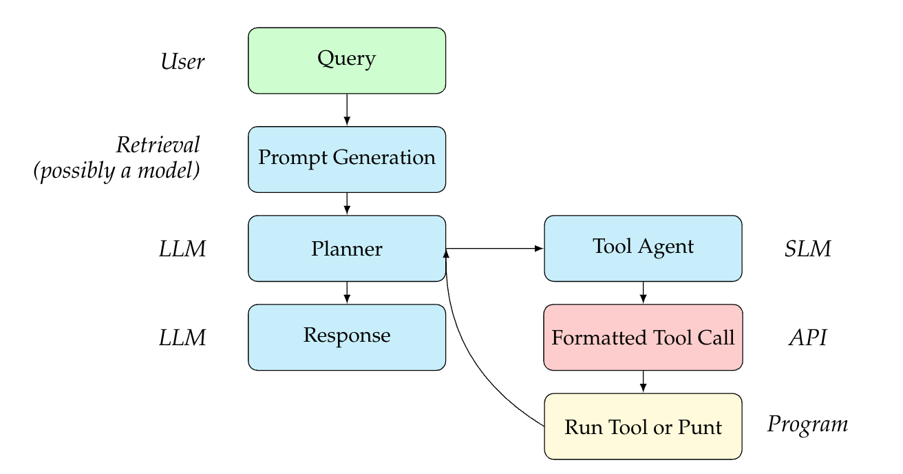
This diagram illustrates a workflow for an agent system, likely involving Large Language Models (LLMs) and tools. It depicts the flow of information from a user query through several processing stages to a final output. The diagram uses rectangular boxes to represent components and arrows to indicate the direction of data flow.
### Components/Axes
The diagram consists of the following components, arranged in a roughly linear flow from top to bottom, with a feedback loop:
* **User:** Initiates the process with a "Query".
* **Retrieval (possibly a model):** Receives the query and generates a "Prompt Generation".
* **LLM:** First instance, receives the prompt and passes it to the "Planner".
* **Planner:** Processes the prompt and interacts with the "Tool Agent".
* **Tool Agent:** Receives input from the Planner and generates a "Formatted Tool Call".
* **LLM:** Second instance, receives the "Response" from the Planner.
* **Formatted Tool Call:** Sends the formatted call to the "API".
* **API:** Executes the call and passes the result to the "Run Tool or Punt".
* **Run Tool or Punt:** Executes the tool or passes control back to the Planner.
Additionally, the diagram includes labels indicating the underlying technologies or models used:
* **SLM:** Associated with the Tool Agent.
* **Program:** Associated with the "Run Tool or Punt" component.
### Detailed Analysis or Content Details
The diagram shows a clear sequence of operations:
1. A "Query" originates from the "User".
2. The "Retrieval" component transforms the query into a "Prompt Generation".
3. The first "LLM" processes the prompt and sends it to the "Planner".
4. The "Planner" interacts with the "Tool Agent" (a bidirectional arrow indicates a feedback loop).
5. The "Tool Agent" generates a "Formatted Tool Call" and sends it to the "API".
6. The "API" executes the call and sends the result to the "Run Tool or Punt".
7. The "Run Tool or Punt" either executes the tool or returns control to the "Planner".
8. The second "LLM" generates a "Response".
The bidirectional arrow between the "Planner" and "Tool Agent" suggests an iterative process where the Planner might refine its requests to the Tool Agent based on the Tool Agent's responses.
### Key Observations
The diagram highlights the integration of LLMs with external tools through an API. The feedback loop between the Planner and Tool Agent suggests a dynamic interaction where the agent can adapt its actions based on the results of tool calls. The inclusion of "Run Tool or Punt" indicates a mechanism for handling cases where a tool cannot fulfill the request.
### Interpretation
This diagram represents a common architecture for building intelligent agents that can leverage external tools to perform complex tasks. The use of LLMs for planning and response generation, combined with the ability to call APIs, allows the agent to go beyond simple text-based interactions and interact with the real world. The feedback loop between the Planner and Tool Agent is crucial for enabling the agent to learn and improve its performance over time. The "Run Tool or Punt" component is a safety net, preventing the agent from getting stuck in situations where it cannot fulfill a request. The diagram suggests a modular design, where each component can be independently developed and updated. This architecture is well-suited for building agents that can handle a wide range of tasks and adapt to changing environments.