## System Architecture Diagram: LLM-Based Tool-Augmented Query Processing
### Overview
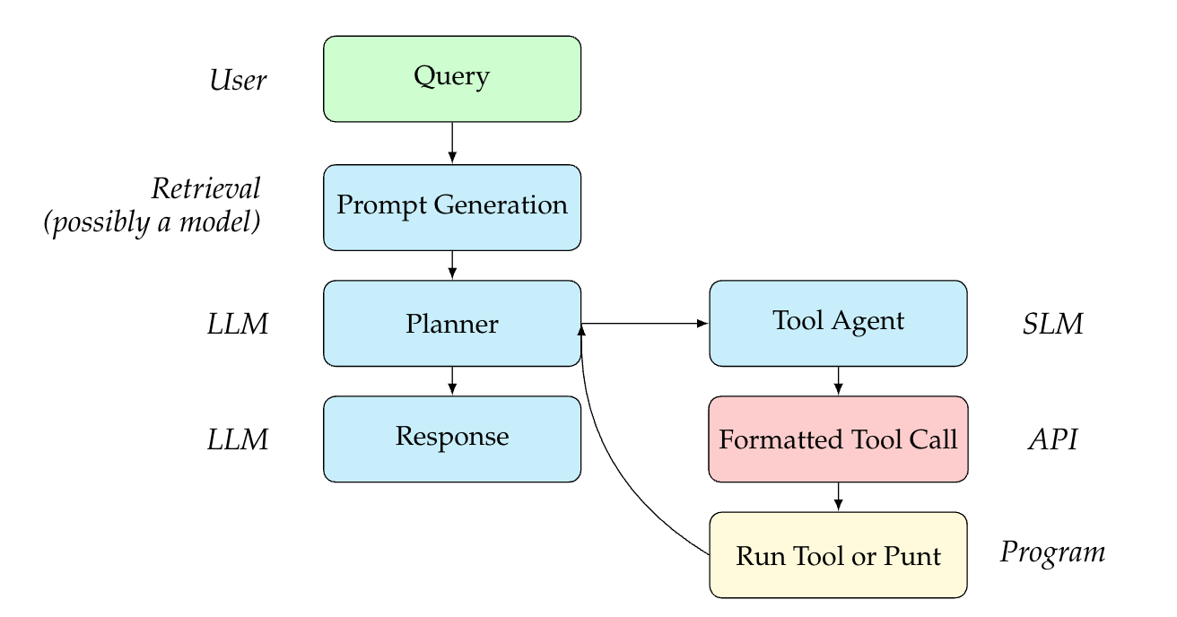
This diagram illustrates a multi-stage system architecture for processing user queries using Large Language Models (LLMs) and Small Language Models (SLMs) integrated with external tools. The flow begins with a user query and proceeds through retrieval, planning, and tool execution phases, with a feedback loop for iterative refinement.
### Components/Axes
The diagram is organized into labeled columns and rows, with color-coded boxes representing different system components. Arrows indicate the direction of data flow and control.
**Left Column (Actors/Systems):**
* **User**: Positioned at the top-left.
* **Retrieval (possibly a model)**: Positioned below "User".
* **LLM**: Appears twice, labeling the "Planner" and "Response" boxes.
* **SLM**: Labels the "Tool Agent" box.
* **API**: Labels the "Formatted Tool Call" box.
* **Program**: Labels the "Run Tool or Punt" box.
**Main Flow (Central & Right Columns):**
The process flows vertically and horizontally through the following components:
1. **Query** (Green box, top-center): The starting point, receiving input from the "User".
2. **Prompt Generation** (Light blue box, below "Query"): Receives input from "Query". Associated with the "Retrieval" system.
3. **Planner** (Light blue box, below "Prompt Generation"): Receives input from "Prompt Generation". Associated with an "LLM".
4. **Response** (Light blue box, below "Planner"): Receives input from "Planner". Associated with an "LLM".
5. **Tool Agent** (Light blue box, to the right of "Planner"): Receives input from "Planner". Associated with an "SLM".
6. **Formatted Tool Call** (Pink box, below "Tool Agent"): Receives input from "Tool Agent". Associated with an "API".
7. **Run Tool or Punt** (Yellow box, below "Formatted Tool Call"): Receives input from "Formatted Tool Call". Associated with a "Program".
**Connections & Flow:**
* A primary vertical flow exists: `Query` -> `Prompt Generation` -> `Planner` -> `Response`.
* A secondary branch flows from `Planner` to `Tool Agent` -> `Formatted Tool Call` -> `Run Tool or Punt`.
* A critical feedback loop exists: An arrow flows from `Run Tool or Punt` back to the `Planner`, indicating that the result of tool execution (or a decision to "punt") informs the planning stage for potential iteration.
### Detailed Analysis
The diagram defines a clear sequence of operations and the responsible system for each step:
1. **Input Stage**: The `User` provides a `Query`.
2. **Retrieval & Preparation Stage**: The `Retrieval` system (potentially a model) performs `Prompt Generation` based on the query.
3. **Planning & Decision Stage**: An `LLM`-based `Planner` receives the generated prompt. It has two potential output paths:
* **Direct Response Path**: The `Planner` can generate a `Response` (handled by an `LLM`).
* **Tool Use Path**: The `Planner` can delegate to a `Tool Agent` (an `SLM`).
4. **Tool Execution Stage**:
* The `Tool Agent` creates a `Formatted Tool Call` (structured for an `API`).
* A `Program` then executes the action: `Run Tool or Punt`. "Punt" implies a fallback or放弃 action if the tool cannot be run.
5. **Feedback Loop**: The outcome from `Run Tool or Punt` is fed back into the `Planner`, enabling the system to adjust its plan based on the tool's result or failure.
### Key Observations
* **Hybrid Model Architecture**: The system explicitly differentiates between a large `LLM` (for planning and response generation) and a smaller `SLM` (for the specialized task of acting as a tool agent).
* **Separation of Concerns**: Each box has a distinct, single responsibility (e.g., planning vs. formatting a tool call vs. execution).
* **Iterative Refinement**: The feedback loop from the execution stage back to the planner is a central feature, suggesting the system is designed for multi-step reasoning or correction.
* **Fallback Mechanism**: The label "Run Tool **or Punt**" explicitly includes a contingency path, indicating robustness in the design.
### Interpretation
This diagram represents a sophisticated **agentic workflow** for an AI system. It moves beyond a simple request-response model by incorporating:
1. **Tool Use**: The ability to interact with external APIs or programs.
2. **Planning**: An LLM that reasons about *how* to solve a query, deciding whether to answer directly or use a tool.
3. **Specialization**: Using a smaller, likely more efficient model (SLM) for the specific task of interfacing with tools.
4. **Iteration**: The feedback loop allows the system to learn from the outcome of a tool call and refine its approach, mimicking a human trial-and-error or step-by-step problem-solving process.
The architecture suggests a system designed for complex tasks that require up-to-date information (via tools), precise calculations, or interaction with external services, where the core LLM's knowledge might be insufficient or static. The clear delineation of components (User, Retrieval, LLM, SLM, API, Program) provides a blueprint for implementing a modular and maintainable AI agent.