## Network Diagram: Hierarchical System Architecture with Bidirectional Z-Layer Interactions
### Overview
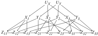
The diagram depicts a multi-layered network structure with hierarchical flow from top to bottom, featuring bidirectional interactions in the bottom layer. It consists of three primary tiers:
1. **Top Layer**: Two source nodes labeled `U_X` (upper-left) and `U_Y` (upper-right).
2. **Middle Layer**: Six nodes (`X1`, `X2`, `X3`, `Y1`, `Y2`, `Y3`) arranged in two rows beneath the top layer.
3. **Bottom Layer**: A 3x3 grid of nodes labeled `Z11` to `Z33`, with bidirectional arrows between adjacent nodes.
### Components/Axes
- **Nodes**:
- **Top Layer**: `U_X`, `U_Y` (no outgoing bidirectional arrows).
- **Middle Layer**: `X1`, `X2`, `X3` (left row); `Y1`, `Y2`, `Y3` (right row).
- **Bottom Layer**: `Z11`, `Z12`, `Z13` (first row); `Z21`, `Z22`, `Z23` (second row); `Z31`, `Z32`, `Z33` (third row).
- **Connections**:
- **Top to Middle**: Unidirectional arrows from `U_X` to `X1`, `X2`, `X3`; from `U_Y` to `Y1`, `Y2`, `Y3`.
- **Middle to Bottom**: Unidirectional arrows from `X1` to `Z11`, `Z12`, `Z13`; `X2` to `Z21`, `Z22`, `Z23`; `X3` to `Z31`, `Z32`, `Z33`. Similarly, `Y1` to `Z11`, `Z12`, `Z13`; `Y2` to `Z21`, `Z22`, `Z23`; `Y3` to `Z31`, `Z32`, `Z33`.
- **Bottom Layer**: Bidirectional arrows between adjacent `Z` nodes (e.g., `Z11`↔`Z12`, `Z12`↔`Z13`, `Z21`↔`Z22`, etc.), forming a grid-like mesh.
### Detailed Analysis
- **Flow Direction**:
- Top-down flow from `U_X`/`U_Y` to `X`/`Y` nodes, then to `Z` nodes.
- Bidirectional interactions in the `Z` layer suggest mutual dependencies or feedback loops.
- **Grid Structure**:
- The `Z` nodes form a 3x3 matrix, with each node connected to its horizontal and vertical neighbors.
- No diagonal connections (e.g., `Z11` not connected to `Z22`).
### Key Observations
1. **Hierarchical Flow**: Information/resources originate at `U_X`/`U_Y`, propagate through `X`/`Y` nodes, and terminate in the `Z` grid.
2. **Bidirectional Z-Layer**: The `Z` nodes exhibit reciprocal relationships, unlike the unidirectional flow in upper layers.
3. **Symmetry**: The `X` and `Y` nodes mirror each other in connections to `Z` nodes (e.g., `X1` and `Y1` both connect to `Z11`, `Z12`, `Z13`).
### Interpretation
This diagram likely represents a system architecture where:
- **Top Layer (`U_X`, `U_Y`)**: Acts as primary input sources (e.g., user inputs, external data streams).
- **Middle Layer (`X`, `Y`)**: Intermediate processors or transformers that route data to the `Z` layer.
- **Bottom Layer (`Z`)**: A grid of nodes with bidirectional interactions, possibly representing a shared resource pool, consensus mechanism, or feedback-driven subsystem.
The bidirectional `Z` connections imply that nodes in this layer exchange information or resources in both directions, enabling dynamic adjustments or collaborative processing. This structure could model systems like distributed computing networks, neural networks with feedback layers, or organizational workflows with cross-functional dependencies.
No numerical data or legends are present; the diagram focuses on structural relationships rather than quantitative metrics.