## Diagram: Task a48eeaf7 (Input/Output Transformation)
### Overview
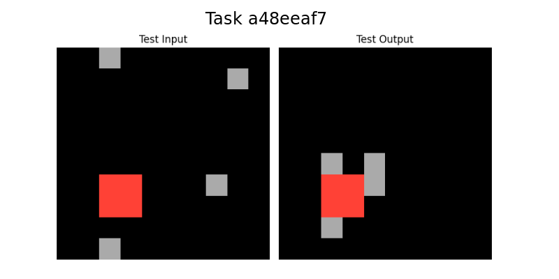
The image depicts a two-panel comparison labeled "Test Input" (left) and "Test Output" (right). Both panels feature a black background with geometric shapes: a red square and multiple gray squares. The arrangement of shapes differs between panels, suggesting a transformation or processing step.
### Components/Axes
- **Title**: "Task a48eeaf7" (centered at the top).
- **Panels**:
- **Test Input**: Left panel with a red square and four gray squares.
- **Test Output**: Right panel with a red square and four gray squares.
- **No axes, legends, or numerical scales are present.**
### Detailed Analysis
#### Test Input (Left Panel):
- **Red Square**: Positioned at the bottom-left quadrant.
- **Gray Squares**:
1. Top-left quadrant.
2. Top-right quadrant.
3. Middle-right quadrant.
4. Bottom-left quadrant (overlapping with the red square).
#### Test Output (Right Panel):
- **Red Square**: Moved to the center-left quadrant.
- **Gray Squares**:
1. Top-left quadrant.
2. Top-right quadrant.
3. Middle-right quadrant.
4. Bottom-left quadrant (now separated from the red square).
#### Spatial Relationships:
- The red square shifts **rightward** by approximately 25% of the panel width.
- Gray squares in the output are repositioned to avoid overlapping with the red square.
- No new shapes are introduced; only positional adjustments occur.
### Key Observations
1. **Red Square Movement**: The red square’s horizontal displacement suggests a directional transformation rule.
2. **Gray Square Rearrangement**: Gray squares maintain their quadrant distribution but adjust spacing to avoid collision with the red square.
3. **No Color Changes**: All shapes retain their original colors (red/gray).
### Interpretation
The diagram likely illustrates a **spatial reasoning task** where an input configuration (Test Input) is processed to produce an output configuration (Test Output). The red square’s movement and the gray squares’ repositioning imply:
- **Collision Avoidance**: The system prioritizes separating the red square from gray squares in the output.
- **Positional Logic**: The red square’s central placement in the output may indicate a "focus" or "anchor" point for subsequent operations.
- **Minimalist Design**: The absence of labels or legends suggests the task relies on visual pattern recognition rather than explicit instructions.
This could model scenarios like object avoidance in robotics, layout optimization, or rule-based spatial transformations.