## Collage of Experimental Room Setups with Spatial Markers
### Overview
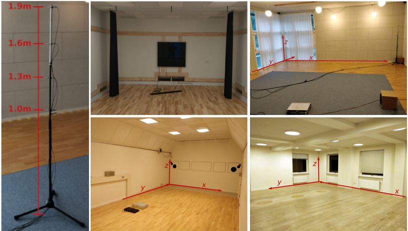
The image is a collage of five photographs depicting different experimental room configurations, each annotated with spatial axes (x, y, z) and measurement markers. The leftmost image shows a vertical calibration pole with height markers, while the remaining four images display room layouts with labeled axes and equipment placements.
### Components/Axes
1. **Left Image (Calibration Pole)**:
- Vertical pole with red height markers at **1.0m**, **1.3m**, **1.6m**, and **1.9m**.
- Positioned on a blue carpeted floor adjacent to a gray wall.
2. **Top-Center Image (Room A)**:
- Axes labeled **x** (horizontal), **y** (vertical), and **z** (depth).
- Features: Wooden flooring, black acoustic curtains, mounted flat-screen TV, and a tripod-mounted camera.
3. **Top-Right Image (Room B)**:
- Axes labeled **x** (horizontal), **y** (vertical), and **z** (depth).
- Features: Light-colored wooden flooring, white walls, large windows with sheer curtains, and a projector on a gray mat.
4. **Bottom-Left Image (Room C)**:
- Axes labeled **x** (horizontal), **y** (vertical), and **z** (depth).
- Features: White walls with acoustic foam panels, recessed ceiling lights, and a tripod-mounted camera.
5. **Bottom-Right Image (Room D)**:
- Axes labeled **x** (horizontal), **y** (vertical), and **z** (depth).
- Features: Light wooden flooring, white walls with recessed lighting, and two windows with partially closed blinds.
### Detailed Analysis
- **Calibration Pole**: The pole in the left image serves as a reference for vertical measurements, with markers spaced at **0.3m intervals** (1.0m to 1.9m). The pole’s base is anchored to a tripod, suggesting use in height calibration for equipment.
- **Room A**: The TV is mounted at the far end of the room, aligned with the **z-axis** (depth). The tripod is positioned near the **y-axis** (vertical), likely for camera stabilization.
- **Room B**: The projector is centered on the gray mat, with the **x-axis** extending toward the window. The **z-axis** (depth) aligns with the wall-mounted projector.
- **Room C**: The tripod is placed near the **y-axis** (vertical), with acoustic foam panels on the walls to reduce sound reflection. The **z-axis** (depth) extends toward the far wall.
- **Room D**: The **x-axis** spans the room’s width, while the **z-axis** (depth) aligns with the windows. The recessed lighting suggests controlled illumination for experiments.
### Key Observations
1. **Consistent Axis Labeling**: All rooms use the same coordinate system (x, y, z), indicating standardized spatial referencing across experiments.
2. **Equipment Placement**: Tripods and cameras are consistently positioned near the **y-axis** (vertical), suggesting focus on vertical measurements or stabilization.
3. **Acoustic Treatments**: Rooms A and C include sound-dampening materials (curtains, foam panels), implying audio-sensitive experiments.
4. **Lighting Variations**: Rooms B and D have natural light sources (windows), while Room C uses artificial lighting, indicating controlled lighting conditions.
### Interpretation
The collage illustrates a controlled experimental environment designed for spatial and sensory studies. The consistent use of axes and calibration markers suggests a focus on **3D spatial mapping** or **human movement tracking**. The presence of acoustic treatments and lighting controls implies experiments requiring **minimized environmental interference**, such as robotics testing, VR calibration, or behavioral studies. The calibration pole’s precise height markers further support applications requiring **vertical alignment accuracy**, such as drone testing or optical sensor calibration.